nghakrmyk
-
Posts
13 -
Joined
-
Last visited
Everything posted by nghakrmyk
-
Hi all - I expect this has already been covered many times, but I'm still left scratching my head at how I can incorporate consistent VCLs across a new loft dormer where a warm flat roof is used alongside timber cavity walls. I can't seem to find much by way of details that show this being achieved. In particular, is the ideal scenario that a VCL for a warm roof, ie above the bottom deck, would join/lap the VCL on the inside of a timber cavity wall? This seems impossible to achieve around ceiling joists. Is the practical alternative that the VCL is just kept internal, i.e., on the warm side of the timber cavity walls and above the roof plasterboard but under the joists? If so, should the bottom deck VCL be removed so as to not trap air between the two?
-
I have since spent a bit more time on EWI and am realising this is maybe not a simple question. It seems wood fibre and EPS are the more common options but I will have to manage the build up carefully as there is only c.100mm total for insulation and tiles etc ie between the outside of the internal skin of the existing brick wall below (which is what the new stud wall is being built off) and the external brick wall. Either way any insight / assistance would be greatly appreciated.
-
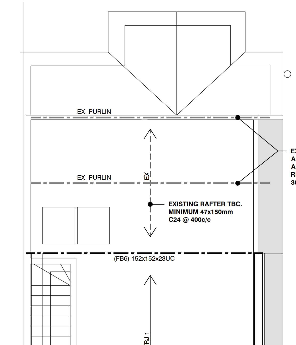
Hi all - unsure if best to put this here or in heat insulation. What are people’s thoughts on a timber cavity wall build up (with hung slates) where I may need to add insulation to the outside of the wall as well as in between and in front of the studs. I’m looking at roughly 62.5mm insulated plasterboard inside, 100mm PIR inside 100mm studs and 50mm PIR outside. I might be able to get away with just the insulation outside (and then a proper separate VCL inside) ie do away with the insulated plasterboard but TBC. The issue I’m facing is that a small section of a steel beam supporting the outermost wall of an L shaped outrigger dormer will be above the existing roof line and therefore essentially exposed to the outside elements if not insulated (see red box in the picture below which hopefully makes sense). It might be overkill but just trying to make sure potential condensation is managed. So far I had the following questions: - Is PIR ok to use as the outside insulation? Foil backed? - if so, what’s the correct build up for the outside element? - do I need to cross batten for slates? Any input would be greatly appreciated.

-
Great, thanks - is that just in case the mortar fails? I was assuming we’d need it to be breathable so it’s the same profile as the rest of the wall, eg spacetherm. I’ll have some knocking around as we need it elsewhere. I don’t believe that’s considered absorbent? Build up would then be - spacetherm (eg 20mm) patched over the steel end with some overlap. Bricks (trimmed if needed) fitted on top. I’m only really worried about condensation - the rest of the house is a thermal sieve.
-
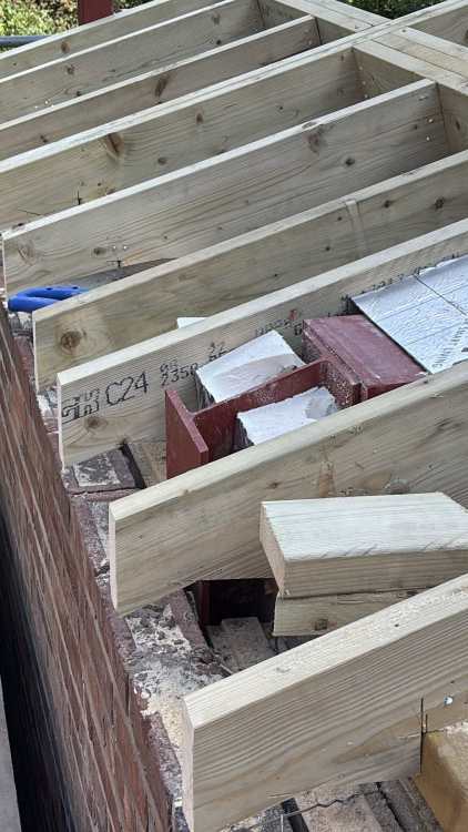
For context, this is how the beam supporting the floor joists has been installed - with a small amount flying over the pad. This steel will sit in the eaves space so I’m less concerned as it should be cold - but wondering if we should add some insulation as belt and braces.
-
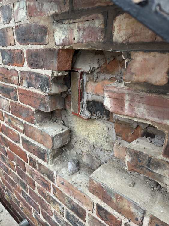
One thing has come to mind actually - the steel beam under the ridge (and another which will support the new floor joists) span the width of the house and sit on pads - so one in the party wall and one in the internal leaf of the existing external double skin wall. A picture is below. It (again) seems the end of the steels sat on the external wall would need insulating as it’s in contact with the outer leaf? 30mm aerogel or a thermal pad would seem to do the trick - but is that what people are really doing?

-
Thanks saveasteading. As an update - the plan is to revert and install the steel beam (152x152) under the existing ridge (180mm deep). More straightforward all round it seems. I should have approx 2580mm from the new floor board to the top of the existing ridge beam with about another 60mm to the underside of the existing ridge cap. So it seems we have enough for a warm roof without needing to change the beam, ie 2x 18mm OSB, 140/150mm PIR, 175mm rafters, plus some change is about 365mm. That leaves approx head height of 2215mm before plasterboard and firrings (these need to be about 60/70mm) but also whether we can use any of the 60mm gap to the top of the ridge cap. I would be very happy if we ended up with 2.2m but seems like we’ll be nearer 2.15m. I’m not actually sure what replacing the beam would achieve as the limiting factor seems to not be the existing beam ie it’s just the ridge height? Both of those would have been measured as part of the initial plans. Thanks again for the replies all - between this and another recent thread, the advice has been invaluable in discussing things with the architects, SEs and builders. I’ll update once there is a plan on the remaining questions above ie managing the warm and cold sides / VCL.
-
I hadn’t, so that’s now with the rest of the questions for the architect / SEs / builders - thanks Nick
-
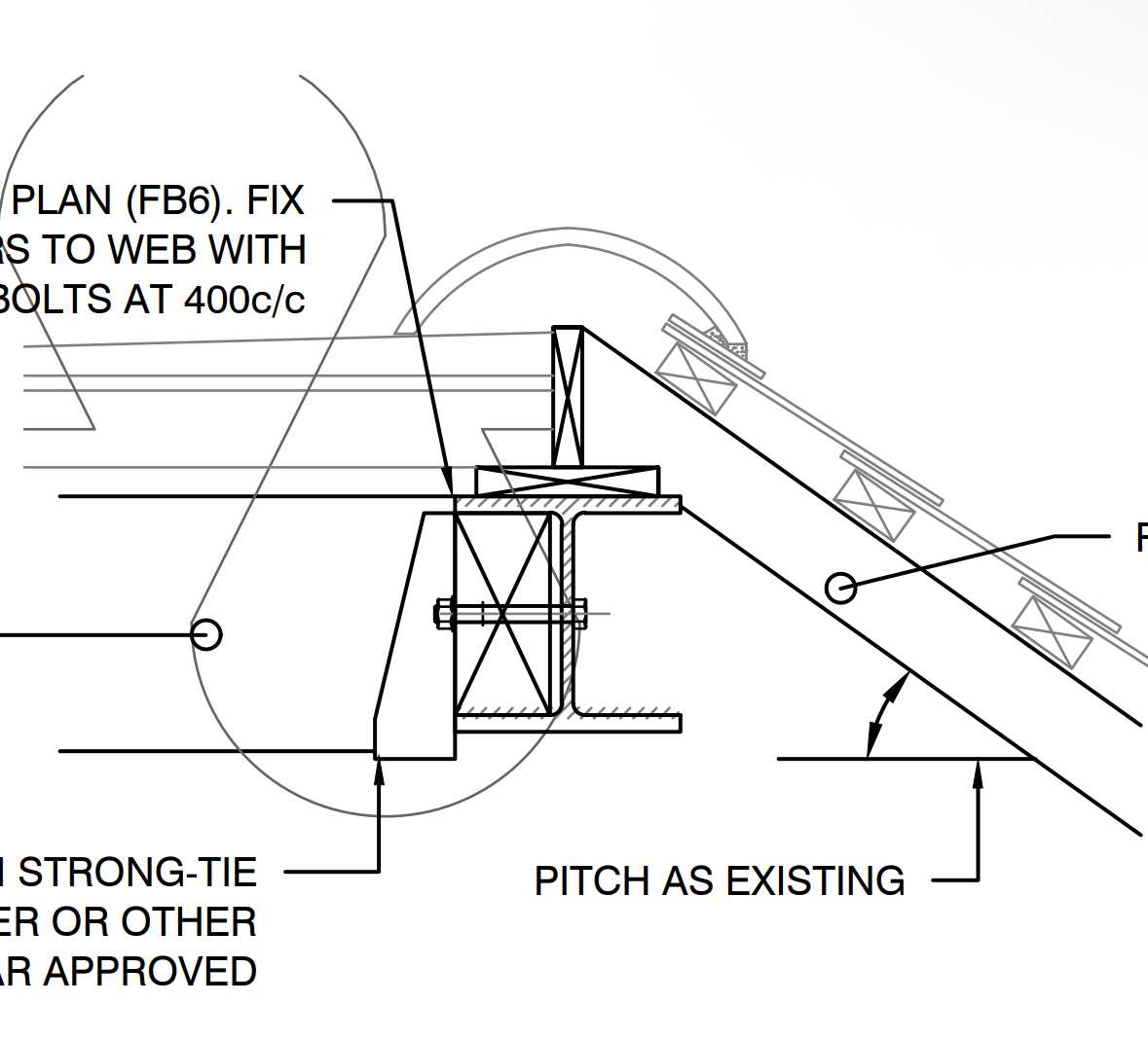
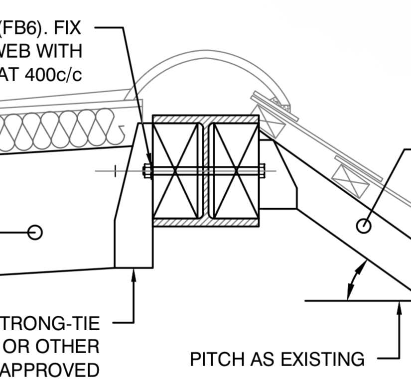
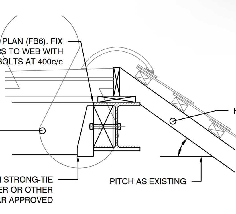
Thanks for the quick replies both - I think it’s back to the drawing board. I have even more questions having stared at it for a few hours - eg how would the cold roof actually vent in this design? The 50mm air gap we were going to leave looks to just flow into the steel webbing (and not up/out). I suspect we’ll go back to what was originally planned (see detail now attached) as I’m not actually sure this stops us doing a warm roof having re-looked at it. There still seem to be questions around bridging though it may just be that the detail dimensions aren’t accurate, eg: - On the cold roof side, the steel flange looks very close to what will be the ventilation gap / essentially be behind no insulation - How to manage the sandwich between cold / warm sides if we can get enough insulation above that cold side edge - How a VCL will stay above deck on the warm side and below the insulation on the cold side - Assume the existing timber ridge beam is not conductive enough to make the steel cold This plan seems to be what’s generally done (I think?) so hopefully more standard though… On your final point JohnMo (ie wall / roof joins) - one side is the party wall so just a single skin and then the neighbour’s cold loft. The other is a double skin wall and no insulation. I’ll ask the architect about that one too.
-
Hi there, I’m converting my Victorian semi loft by adding an L shaped dormer to the rear. We’re trying to get a warm roof on the rear flat section and are just insulating the front existing roof from the inside. To make the most of the available head height, the architect has suggested replacing the existing timber ridge beam with a new steel beam (instead of adding this underneath the existing). I’ve attached a snip of the detail from the structural engineers - the steel beam looks to be underneath the ridge cap ie cold. No one has highlighted whether this should be insulated, and how it could be achieved between the warm roof / cold roof sandwich, so just wanted to see how others have approached this before? The loft work is about to begin so hoping to avoid walking into issues before too late.

-
Steel goal post clearance to top of rafters
nghakrmyk replied to nghakrmyk's topic in Heat Insulation
For anyone interested, a plan has been designed to solve the above 2 points (ie cold column connected to the beam + height of the beam). - The beam is being cut back and rewelded with a crank section to drop the height of the beam + column connection. - A thermal break pad is then being put in the new column/beam connection. - The internal exposed face of the steel will be insulated/covered. With a do over we would have installed the column inside. -
Steel goal post clearance to top of rafters
nghakrmyk replied to nghakrmyk's topic in Heat Insulation
Thanks all. nod - if we used foil, my concern was that it would only be 10mm compressed at the pinch point so not offering much protection. However, there's an air gap benefit ie if we still used a 38mm rafter, we would then have a 38mm air gap (vs 28mm air gap and 20mm PIR)? Not sure if that would be a big difference. Russell / saveasteading - I suspect this is what we'll go for so pack in PIR and foam as much as we can. My concern was really (i) damp / condensation and (ii) minimum gap to the cill, but the immediate reaction suggests I'm maybe over-thinking it? If not clear from the picture, the steel column is not inside the insulation anyway and the column/beam join is not thermally broken, so question how much of a difference this will make in any event. In terms of the measurements, it's a c.150mm difference to the plans so a bit more than I'd like. -
Hi there - I’m looking for some guidance on an extension that is ongoing. There has been a deviation from the original plans and I’m unsure if the builder’s / architect’s solution is going to address the issue (or if I’m asking the right questions). I am extending a Victorian semi with an apex-type wraparound - a steel goal post is to support the existing rear wall. In the drawings / structural calcs, the goal post beam was not cranked and it was intended the top of the beam would sit below the bottom of the rafters. Cold bridging at the top of the steel would have been managed, as I understand, as we’re using a ventilated warm roof. However the builders have now put the steels in, added the rafters and the top corner of the steel beam (where it meets the steel column) is 10mm below the top of the rafters. I had to raise it with the builders (not sure why it wasn’t spotted) and we have now been trying to find a solution. We are also limited in the extent to which we can add height to the roof due to existing 1st floor windows - this gap (ie from the top of the rafter to lowest window cill) is currently c.178mm. Lastly, the roof is setup at a 16 degree pitch. Not much flex as the builders don’t want us to go lower as we’re putting normal veluxes in. A picture is attached which shows the steel corner pinch point. The architect’s suggestion was to add a batten (eg 38mm high) to the rafters to allow for c20mm PIR over the pinch point and a 28mm air gap to the vapour membrane. Then counter battens + battens for slates. This leaves c.80mm to the window cill for flashing - TBC if we could possibly use thinner battens to make it 90mm. I’m concerned 20mm PIR is not much of a solution and that 28mm is not sufficient, but absent changing the beam to a cranked beam so it sits below the rafters, there don’t seem to have many options? Any thoughts would be much appreciated.