


EinTopaz
-
Posts
190 -
Joined
-
Last visited
EinTopaz's Achievements

Regular Member (4/5)
28
Reputation
-
thanks for all the replies guys. I didn't actually know there was a technical term for this so thats reassuring. "Plinth Insulation" ? if I mention that terminology to a EWI company, will they likely know what im referring to? Im surprised it didnt come up when i asked AI. Though the process it walked me through does sound somewhat consistent with how its being described on here.
-
Hello all, Now the temperature has got a little colder, i've noticed the floor in our rear extension appears to be colder than the floor in the rest of the property. Long story short, original property is is suspended floor, extension done 2023, piled, concrete floor floor with 100mm kingspan in there, then 6" concrete over the top, which the inner skin wall was built on. As the floor concrete meets the inner skin block wall with no thermal separation in this case, i suppose the prevention of a bridge here is entirely down to how well the PIR was done in the wall cavity and indeed how low it goes... I can have that inspected etc. But from chatting the problem through with AI, it suggested dealing with this externally rather than trying to mess around with the wall cavity. It suggested running 500mm tall XPS external insulation boards from just below DPC, down into the ground. So in my case... essentially 200mm visible about ground level, 300mm below ground level. Then to hide the visible bit, an angled plinth atop, and brickslips over the front /side faces. Has anyone done this before? Looking at most EWI / Render jobs i can see online they usually run from DPC upwards to avoid a bridge I guess. But in this case is it fine to do from DPC downward? maybe leave a 100mm gap from DPC to where the plinth starts. thanks Ged
-
Fascia Vent Strips & Overhanging Membrane = Problem?
EinTopaz replied to EinTopaz's topic in Roofing, Tiling & Slating
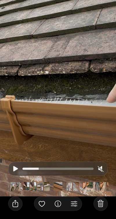
Interesting, lifting up the felt on ours the vents appear to be facing outward away from the brick work, rather than downward.... maybe they'ved used a different type on ours, or installed them back to front? Is that a problem? Photos below.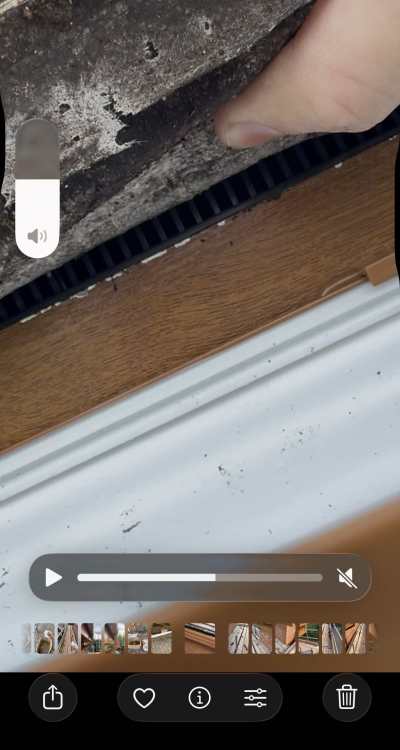
-
Fascia Vent Strips & Overhanging Membrane = Problem?
EinTopaz replied to EinTopaz's topic in Roofing, Tiling & Slating
I'll ask for the eaves guards to go in before the scafff comes down, good call. thanks. -
Fascia Vent Strips & Overhanging Membrane = Problem?
EinTopaz replied to EinTopaz's topic in Roofing, Tiling & Slating
thanks @ProDave will take some snaps when i'm home, it has those over fascia vents on there, but the bitumen is drooped over them and hanging into the gutter. That's my concern that the bitumen is essentially obstructing the air going into those vents. -
Hi all, We've had our old white soffits and fascias replaced this week with UPVC Oak. Our old white soffits were 550mm and were vented (25mm continuous cut outs toward the outer edge). The roofer doing the work has told me they just don't make them that deep in UPVC Oak, so has told me we'll go with a Hollow board soffit instead. Visually I think it looks fine, but obviously not vented. I enquired with the roofer about sufficient ventilation, they said they'd add fascia vent strips as an equivalent ventilation method. However now installed I can see the membrane droops quite low and could be blocking those strips.... again i've enquired, roofer said not a problem. But figured better to get a second opinion on here before the scaffolding all comes down. what do you think? Cheers Ged
-
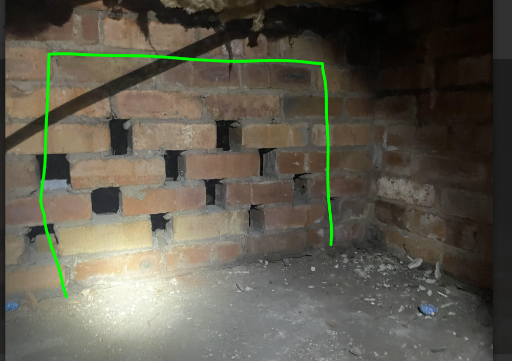
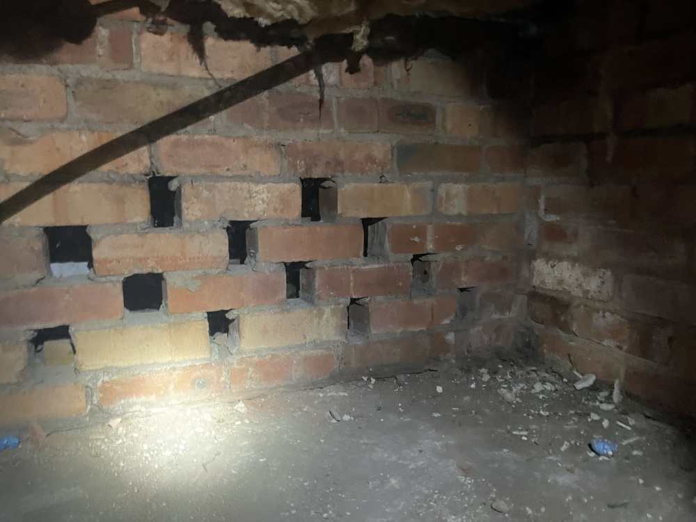
Hi all, Because a bunch of reasons, I need better access to a particular area of the sub floor. The easiest route would be to make some sort of opening in the wall pictured below. I've triple checked and this subfloor wall is supporting the floor only, there is no brick/block wall above it. in that case, what are the steps to open it up? and will it need a specific steel beam? i'd say for comfort sake, 600mm height/width would be fine for me to get through.
-
Void Behind Bay Window Roof - How bad of an issue is this?
EinTopaz replied to EinTopaz's topic in Heat Insulation
We are replacing the soffits and facias on the top floor this summer, so I guess i'll have a look at how exposed/unsealed the tops of the wall cavities are then. -
Void Behind Bay Window Roof - How bad of an issue is this?
EinTopaz replied to EinTopaz's topic in Heat Insulation
thanks, Perhaps only on the surface... been 5 years of finding horrendous workmanship. I feel we're finally at the end of it now (he says) -
Void Behind Bay Window Roof - How bad of an issue is this?
EinTopaz replied to EinTopaz's topic in Heat Insulation
where else would the draughts be coming from? -
Void Behind Bay Window Roof - How bad of an issue is this?
EinTopaz replied to EinTopaz's topic in Heat Insulation
thanks guys, how much of a problem is it if i can only get the PIR closing the outer leaf rather than the inner? Im not sure how good the access will be without removing the entire roof. Which ofcourse i'd rather not. -
Void Behind Bay Window Roof - How bad of an issue is this?
EinTopaz replied to EinTopaz's topic in Heat Insulation
There likely is, but i think it may be even higher up than this, Every bedroom on the 1st floor of this property steps up 100mm towards the front of the house, so I reckon the lintel is in there. All the voids between floor and ceiling have double cavity voids too. Where I think they kept the original bungalow ceiling up, then essentially did another cavity above that. Its an odd one. But either way; is the fix to basically PIR board that huge gap and foam seal? -
Void Behind Bay Window Roof - How bad of an issue is this?
EinTopaz replied to EinTopaz's topic in Heat Insulation
thanks guys. It looks to my eye that neither of the leafs are continuous based on that.... and looks like they'd foamed the outer once but either not all the way across or its failed. For a fix, tiles, battens, felt off.... PIR board wedged in as deep as I can get it, and foam sealed around the edge, will that suffice? For trivia....Worth noting the property used to be a bungalow so those bays will have originally just run into the old roof. It was converted in 2006 so had hoped i wouldn't be finding this but hey ho, it is it what it is. picture of it in its original bungalow form...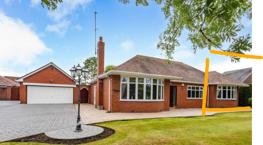
-
Hi all, Was recently looking at replacing the soffits and facias over a front bay window, on closer inspection It looked like there was potentially a void in the outer skin of the wall that the soffits, facias and the roof of the bay window are covering. I decided to take some tiles off to have a better look and did indeed find a void in the outer skin of the wall, and to my eyes looks like the void continues through the inner skin too? (though it'd be good for someone to confirm that). Based on the image and video below, how bad of a problem is this? should I get the roof off and seal this void? Reason I ask is because this bay window is for the dining room, notably the coldest room in the house. So perhaps not a coincidence? Here's a video that shows the void well :- Hole Video Behind Bay And images too:- Bay window in question Void behind the tiled roof. What do you guys think? fine? or bad? or really bad? thanks Ged
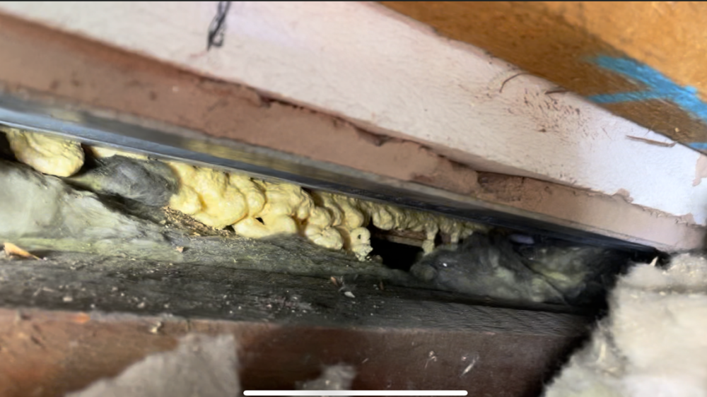
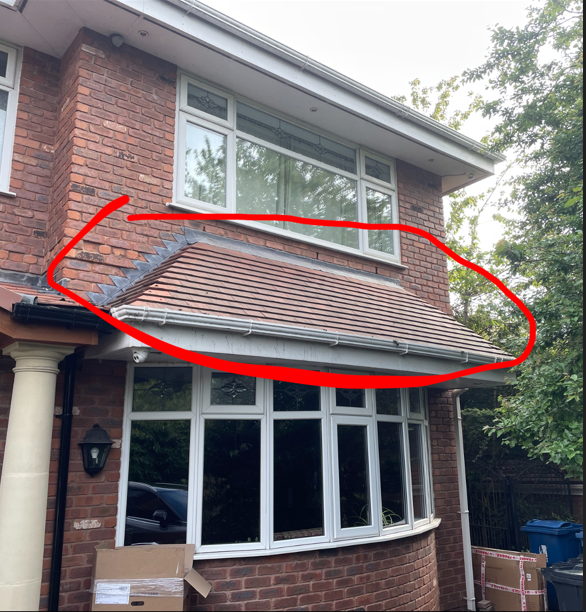
-
Worcester Bosch Greenstar 8000 System Boiler Issues
EinTopaz replied to EinTopaz's topic in Boilers & Hot Water Tanks
Yep, from monitoring i think this is just standard behaviour from modern boilers. Though as part of the test yesterday I did try setting the burner min output% to 45% (default is 14%). It did shave a few minutes off reaching 60c, but i think it also caused further problems with the boiler not being able to properly modulate down once it had hit/exceeded target temp. I need to confirm that today with another test, may've been a coincedence. Yes exactly, thats the behaviour i'd expect to see. If the system doesnt demand as much power as the boiler can give, ie if some of the TRV temps get hit and the radiators turn off, i'd expect the boiler to modulate down, not just carry on and overshoot the temp at 100% output. That just seems ignorant and primitive to me, I agree with you that this doesn't seem like its part of normal programming, this boiler doesnt have a return temp that i can monitor on the LCD, but it must have a sensor inside thats being checked to determine the modulation beyond the flow temp? From memory they have changed a couple sensors already but that was to try and fix the massive difference we had back when the HEX was screwed. Maybe theres more sensors on there that need to swap thats causing this? When i run it now with all the radiators fully on, ive got the target set at 68c, it will overshoot this by 4c, very occasionally it will overshoot it by more and turn the burner off. But that's more rare when all the radiators TRVS are on. When it doesn't trip off, as mentioned previously it will take as long as 30-45 mins to come back down to target. Modulating verrrry slowly as it goes. My own sensor is now 1C difference to the boiler LCD display. That's a good question, do you mean if i change it once the target temp has been reached and everything is stable? i'll give that a try. From memory i dont think it reacts at all to this. Before hex replacement i cant recall, I feel it was still overshooting back then.... it must've been as it was going quite high on the LCD display, why do you ask? do you suspect theres been a problem since they swapped the hex and thats causing the overshooting?


