Rubics
-
Posts
12 -
Joined
-
Last visited
Rubics's Achievements
Member (3/5)
0
Reputation
-
Two main reasons they mentioned. 1) Keep the UFH pipes clean by not allowing radiators to mix with UFH 2) Backup boiler in case one fails. In my head I was hoping that one could do radiators + UFH but this was recommended as gold standard! What hurts is me having to rely on this forum and my network of friends to make things right even after paying the qualified plumbers to fit things properly. how would anyone know if the plumber has done things properly or not these days? End of the day things will work somehow and we trust it all done correctly but only experts could call out faulty installations. Thanks
-
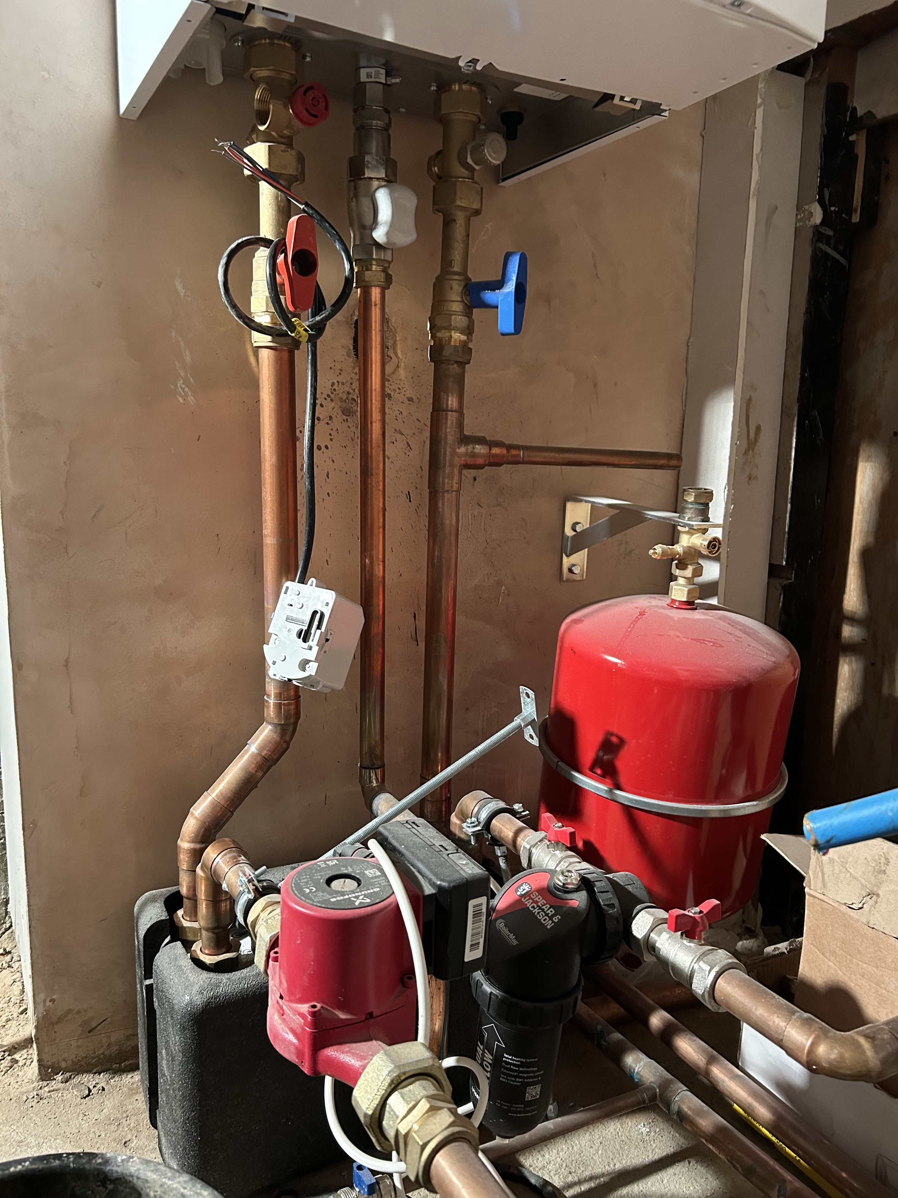
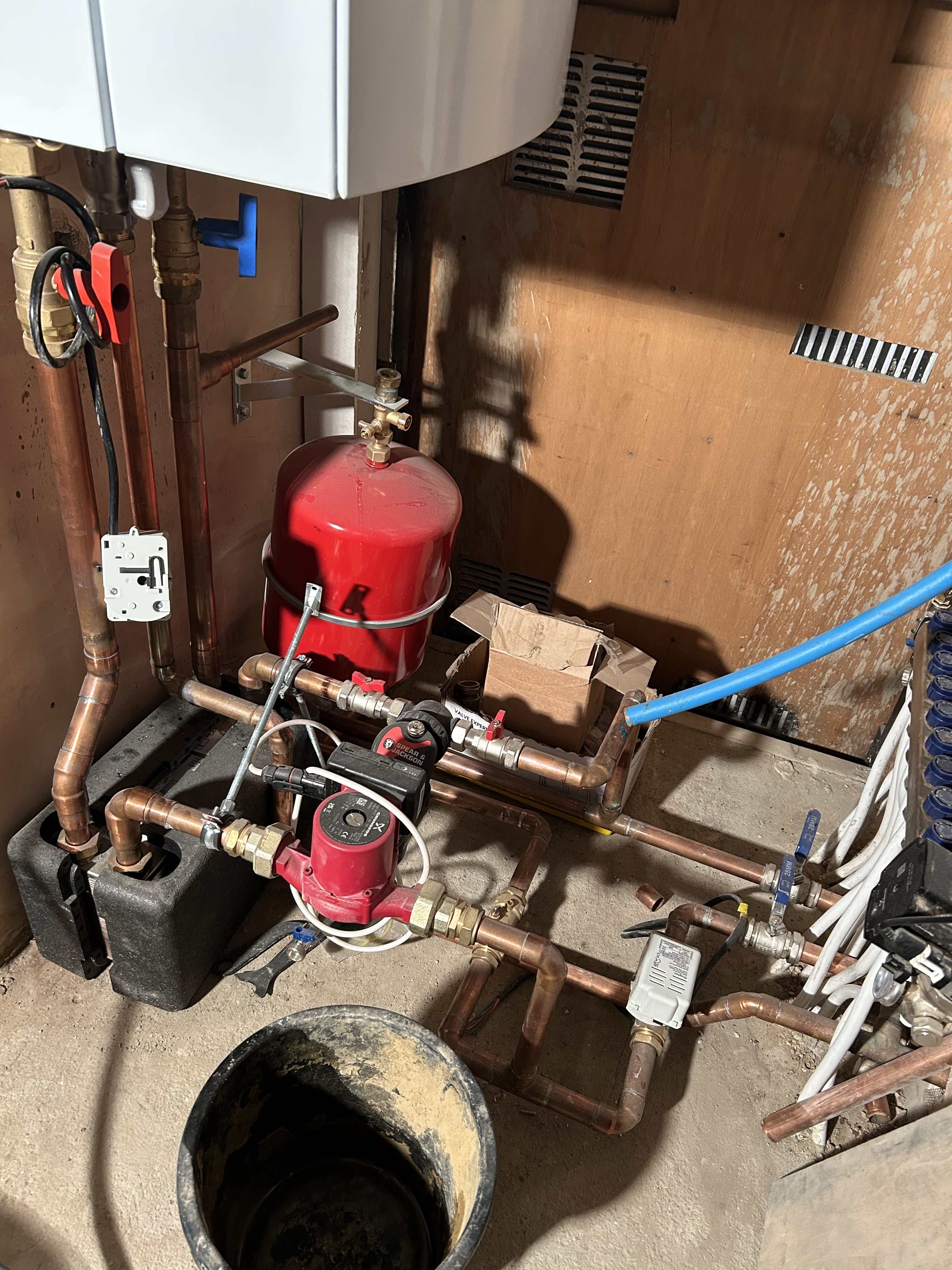
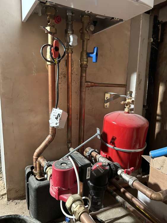
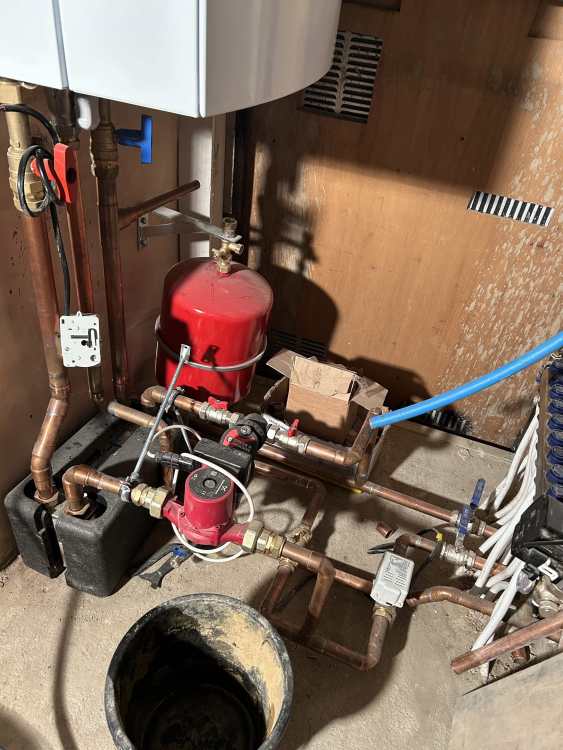
The main system boiler is not feeding any UFH. Its serving around 16 radiators and a new hot water cylinder. The small combi boiler is serving the new UFH section of the house. Thanks
-
-

-

-
We will find out tomorrow as they are coming back to address these concerns. Many thanks. I am also worried about a main system boiler they are working on. Shall I post it here for suggestions or create a new thread as its not to do with UFH? Thanks
-
Thank you. They are coming back tomorrow to make it right. I will post an update soon
-
THanks Nick, I ran it for 10 hours and not much heat output (barely warms up the floor). The plumbers have agreed to make it right whilst keeping the manifold pump and blending valve. The flow rates need to be re-balanced. I can insist them to add the isolation valve as well. Thanks
-
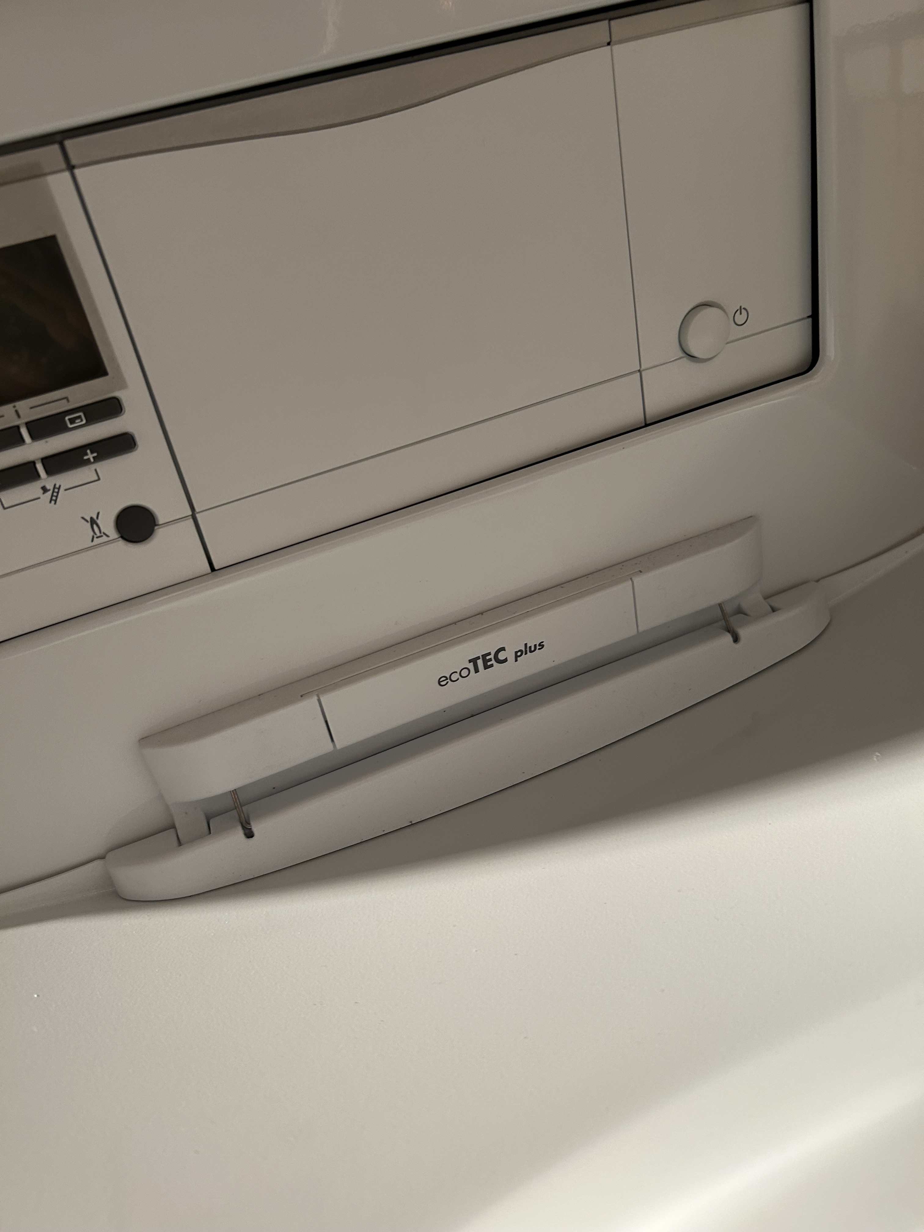
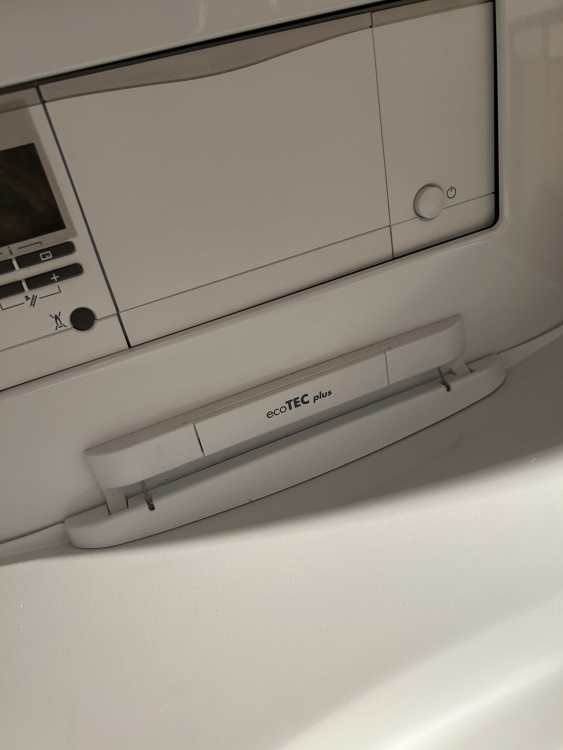
Its a brand new dedicated combi boiler just for the UFH. The make and model is Ideal Logic max combi(2) C24. just one thermostat just to turn it on and off as the UFH is just serving two zones even though we have too many pipes. So its all pipes ON together with no distinction of zones/areas. Thanks
-
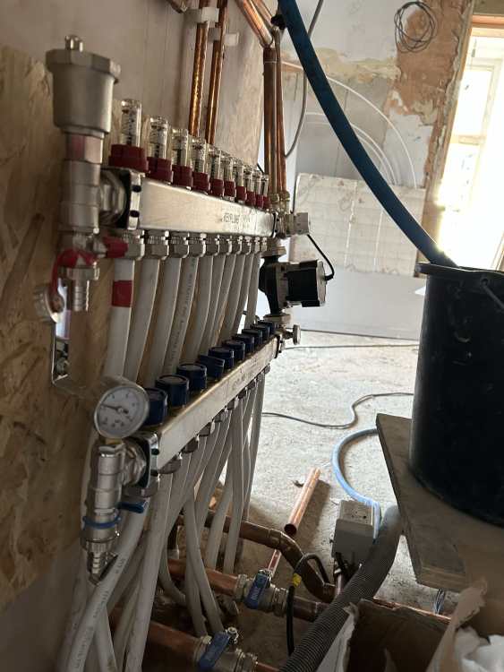
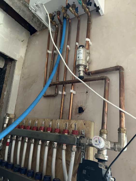
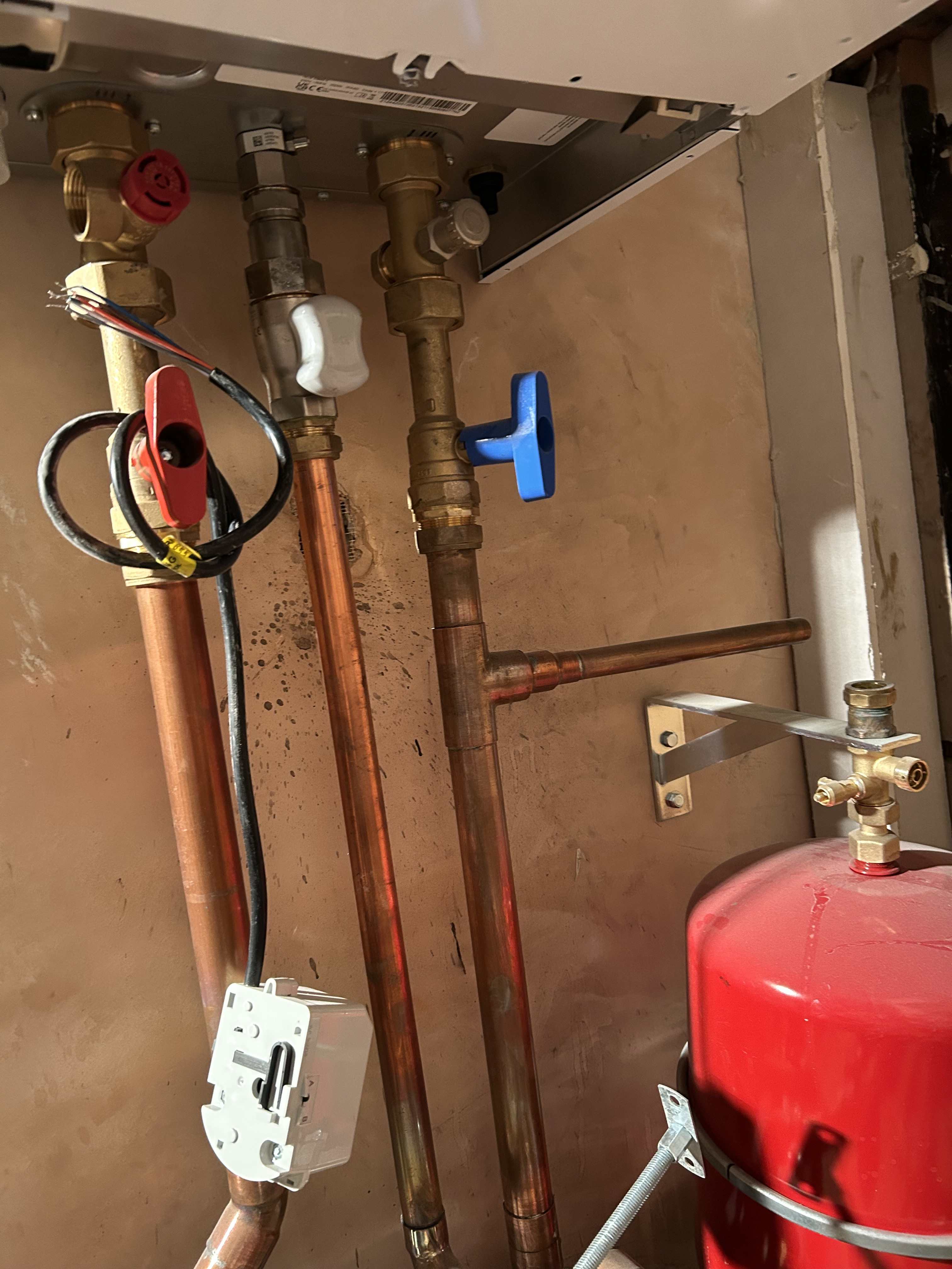
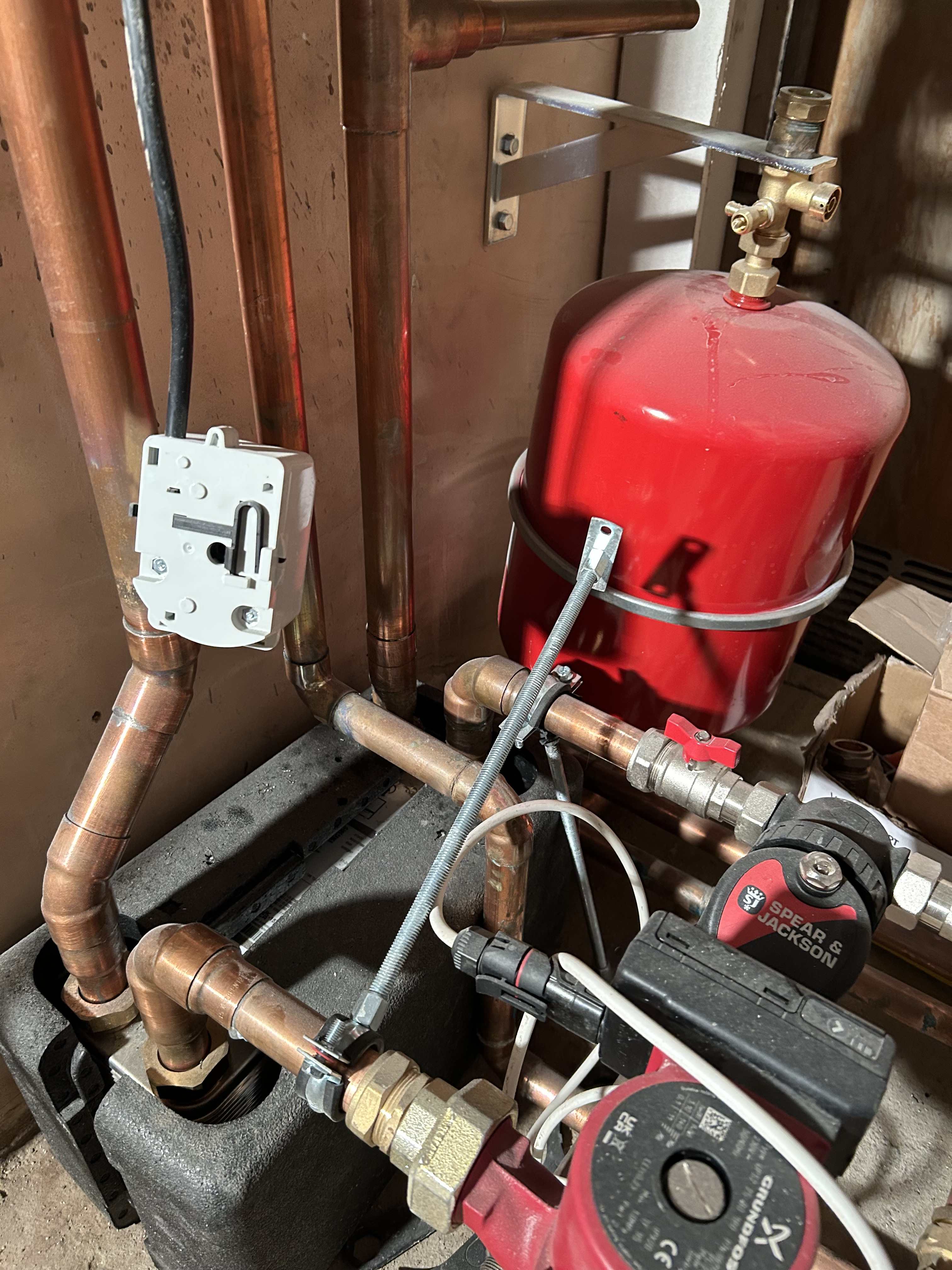
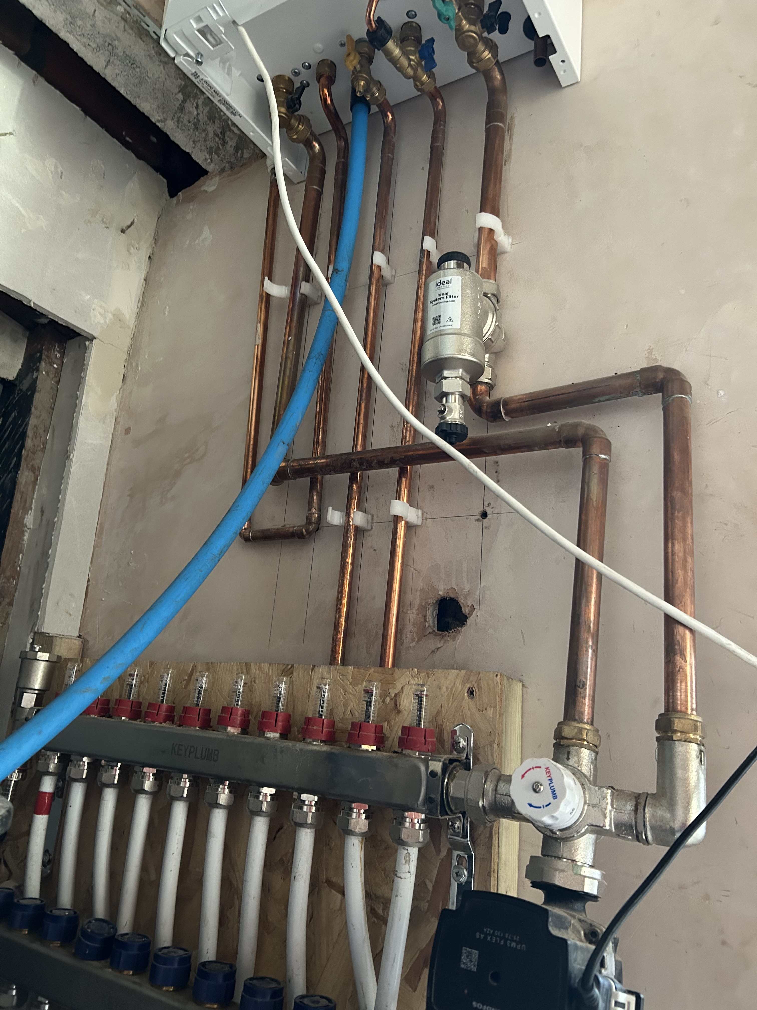
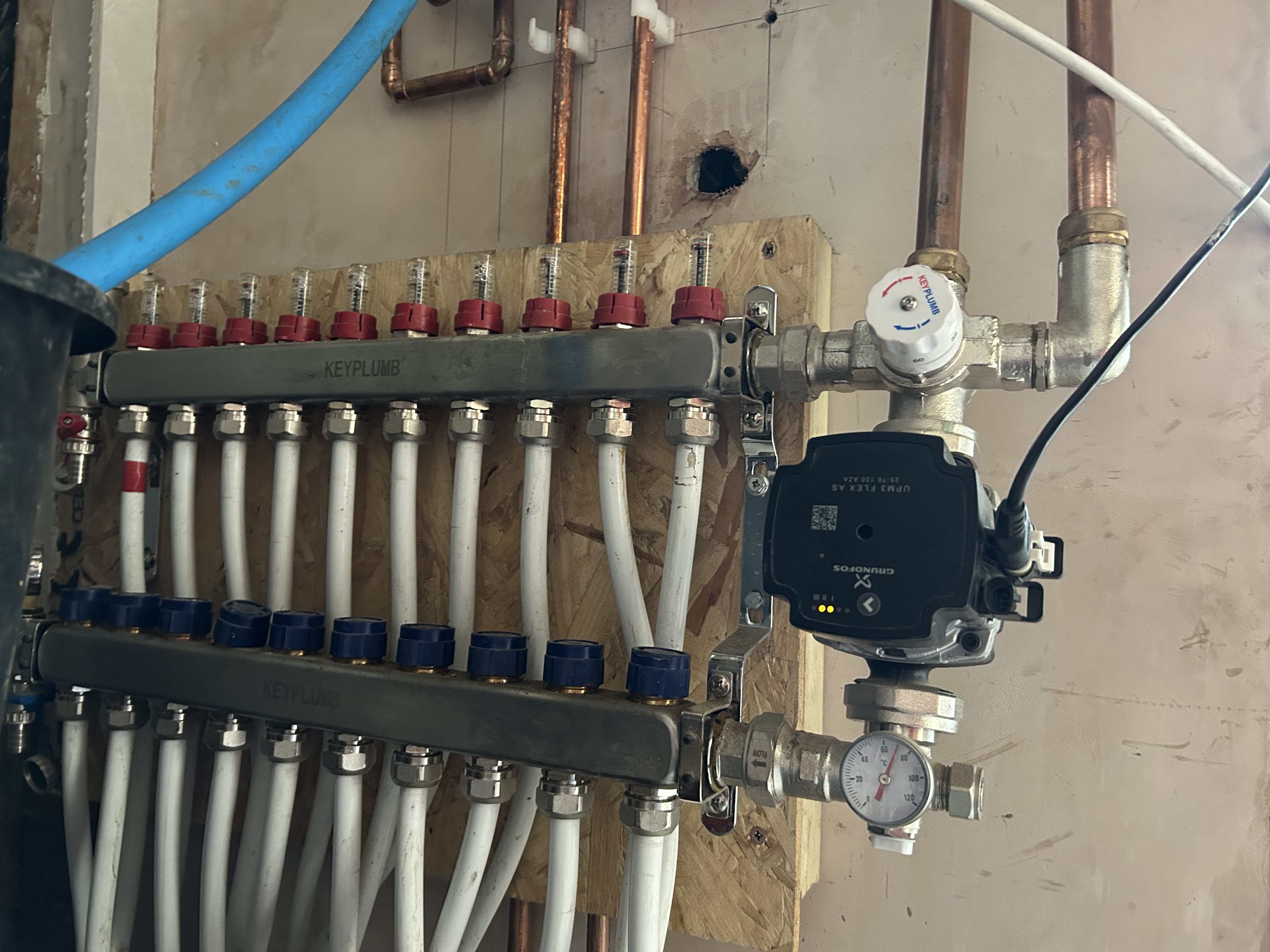
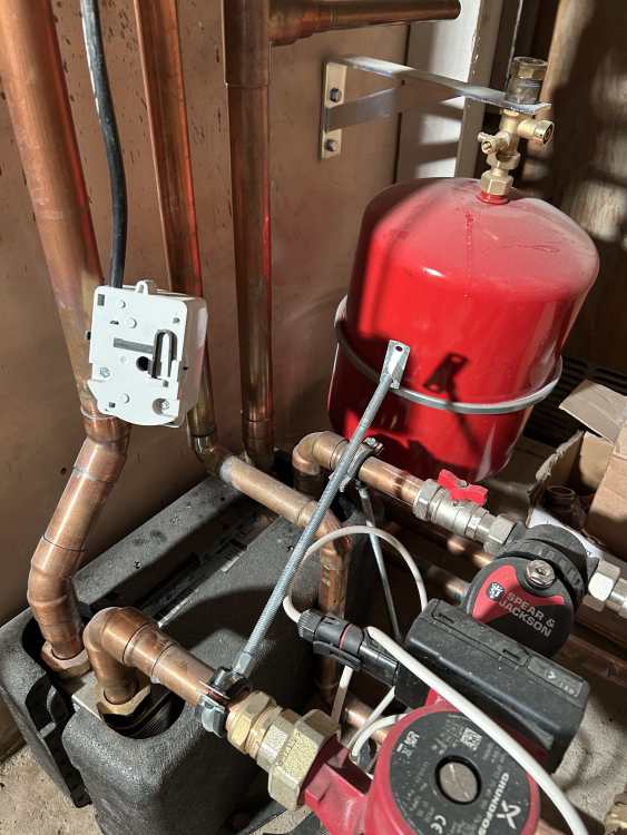
Hi John, Many thanks for taking time to look into this I will suggest them to look into this 'here is zero protection for that pump. It needs a min flow valve or connecting via a close coupled tee' With regards to 'need for the pump and mixer on the manifold at all' - could this benefit from ensuring water pressure to feed 10 100m under floor pipes? It could be that the supplier gave it as a pack and the plumbers went on with installing it. I can see the benefit of saving electricity if the pump and mixer is not required at all. Could you elaborate this 'it just needs connecting the current way about'? Are you saying it needs to connected the other way - mixer output to the flow (red) arm? Your observation on 'missing is isolation valves between pump/mixer and manifold' - i remember seeing the isolation valves which the plumbers dismissed as there are no radiators and no possibility of dirty water entering the UFH pipes. One of the videos I watched yesteday had the isolation valves between the boiler and the mixer pump. Is this where you would recommend the isolation valves? Between the boiler and the pump/mixer and not between the pump/mixer and the manifold? Many thanks
-
Hi Nick, Thanks for your inputs. The 70C is the flow output as its the output from the mixer pump. The plumber buddies (both qualified and gas safe) commissioned it together. Sorry, I am new to these terminologies and I am not aware of the target design/flow temp. I could ask my supplier and find out more details on what they have assumed. For me its only UFH for my new extension and anything beyond that is alien terms (but I am learning now as I am worried about how this is being handled). I do not know whether the flow gauges are doing anything as now the water is flowing in the opposite direction, my understanding is the gauge is no longer capable of doing its job. Pump mounted upside down - I agree, and I dont know whether they will make this right if I request/demand them to make it right. Any suggestions are trashed highlighting the efficiency and modern parts of new boilers and how they can cope with such deviations
-
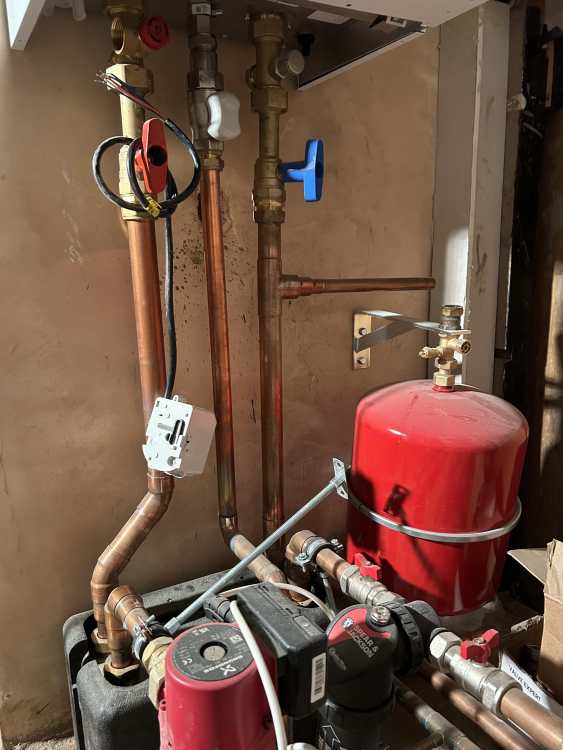
Hello members, thanks for looking into this. I am confused onto why my pair of buddy plumbers have jointly and intentionally switched the manifold flow and return connections. Their initial response was due to space restrictions on the left hand side of the manifold which is no longer the case as there is more space available now to make it right. However, the insist the current installation is just fine and no need to do anything. Could someone help me understand what happens when the hot water output from the mixer pump is connected to the return arm (blue) of the manifold where the actuators are. As a result the water return from the under floor pipes are connected to the flow arm(red) of the manifold. I can see that they have connected the pressure gauge on the return arm of the manifold as this is where the pump is feeding hot water.Wouldn't this setup hinder with the normal and efficient functioning of the actuators and the flow rate controllers? How do I explain this to the knowledgeable plumbers who installed it who think they are right and this current installation is just fine? What problems do you see with such a reversed connection? Please note they have only switched the output of the mixer pump to connect to the return arm of the manifold instead of connecting to the flow arm. In addition, there is no heat adjustments required on the actuators as its all ON or nothing across all zones. Thank you