jamesdiyer
-
Posts
83 -
Joined
-
Last visited
Everything posted by jamesdiyer
-
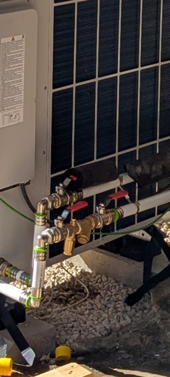
Thanks for suggestion will try. And yes the pipes are on the snagging list (they ran out of insulation). The rubber feet are also incorrect.
-
To pick up the filter situation. I have a standard strainer filter before the ashp. Would it be ok to remove this filter for a short period to test flow rate difference? Or do I run risk?
-
This is a fantastic video by John cantor on dt and flow. And really confirms that I want more flow, to me anyway. I think we will be ok with the current flow we have, but when I want a greater heat demand I will need more flow, and having the ability to flow more - with a modulating pump speed - is never a bad thing. But maybe I've miss understood. Like having a car with a big engine, you might only want it occasionally to overtake, but when you need it you need it. I thinl
-
Yes it's set to auto for pump. Is the fan rate an indication of if the machine is at 100%? Or perhaps it's compressions modulation % I'm doing DHW cycle now and pump is 100%, compressor 70% and flow is 1640l/h / Ft 50.9C / Rt 43.4C ; so 14.26kW at delta 7.5C. It is 19C outside.
-
Thank you very much for this advice. When the installer was here, we set pump to 100% and it flowed 1700l/h around heating circuit. 2000l/h around DHW circuit. Currently I'm Curve 0.6, desired temp 20C, room temp inactive, low flow 25, max flow 50. While I try to get it adjusted. We are a South facing rectangle so I will need to move to active to accommodate for sunny days. No TRVs. Fully open. 1 circuit, branches into two 22mm mains feeding 5 radiators each - upstairs and downstairs. I know I can meet my current heat loss, but I speced a 15kw machine as in a year or two I'll finish renovating the third floor - 100m2 independent apartment and this will need heating. I note your points on getting it working full bore and will try tomorrow. But I'm not sure I can get a kW reading from the software of vaillant screen? Though I guess I can read flow temps and flow rate and calculate.
-
Well 5. But the heat demand is very low currently. I'm not sure how to force the highest heat demand from the hestpump to see what the delta t and max kW produced is.
-
Actually looking the part manual they seem to be full bore and they're 1" so 22 internal but will know when off. If we're talking restrictions, then the plastic 25mm pipe fittings are internal of that. The pipe id is 20 and so you're looking at 15mm inside of the fitting id. But that's a very tiny distance, so I'm not sure it matters? (Everything matters in totality) Annoyingly vaillant Spain seem to be useless, which isn't good. I got some answers from vaillant UK very easily - flow should be targeted at 2000l/h, and send me their installer handbook with figures. Not surprising.
-
Good question. The red ones yes. The blue ones on the heating pipes should have come out during the install but we're left. They were only placed there so I could pressurise the system prior to installer coming to check some repairing I'd done was fine. So they'll come out when he's back.
-
Yes sadly that's so, and parts on the install weren't discussed with me. On another note, my monitor says basic circuit diagram 8. However if I am just with a volumiser and DHW tank, radiators only 1 circuit, should this be 7?
-
The sensor comfort is there temporarily, it's wired and I couldn't decide where to put it - walls are 80cm think. I'm running pure weather compensation. Yes your comment alludes to my first question, I felt 1700l/h is low - and I have a 15kw machine. But others here said running 32mm external 26mm internal plastic pipe over 11m isn't enough bore.
-
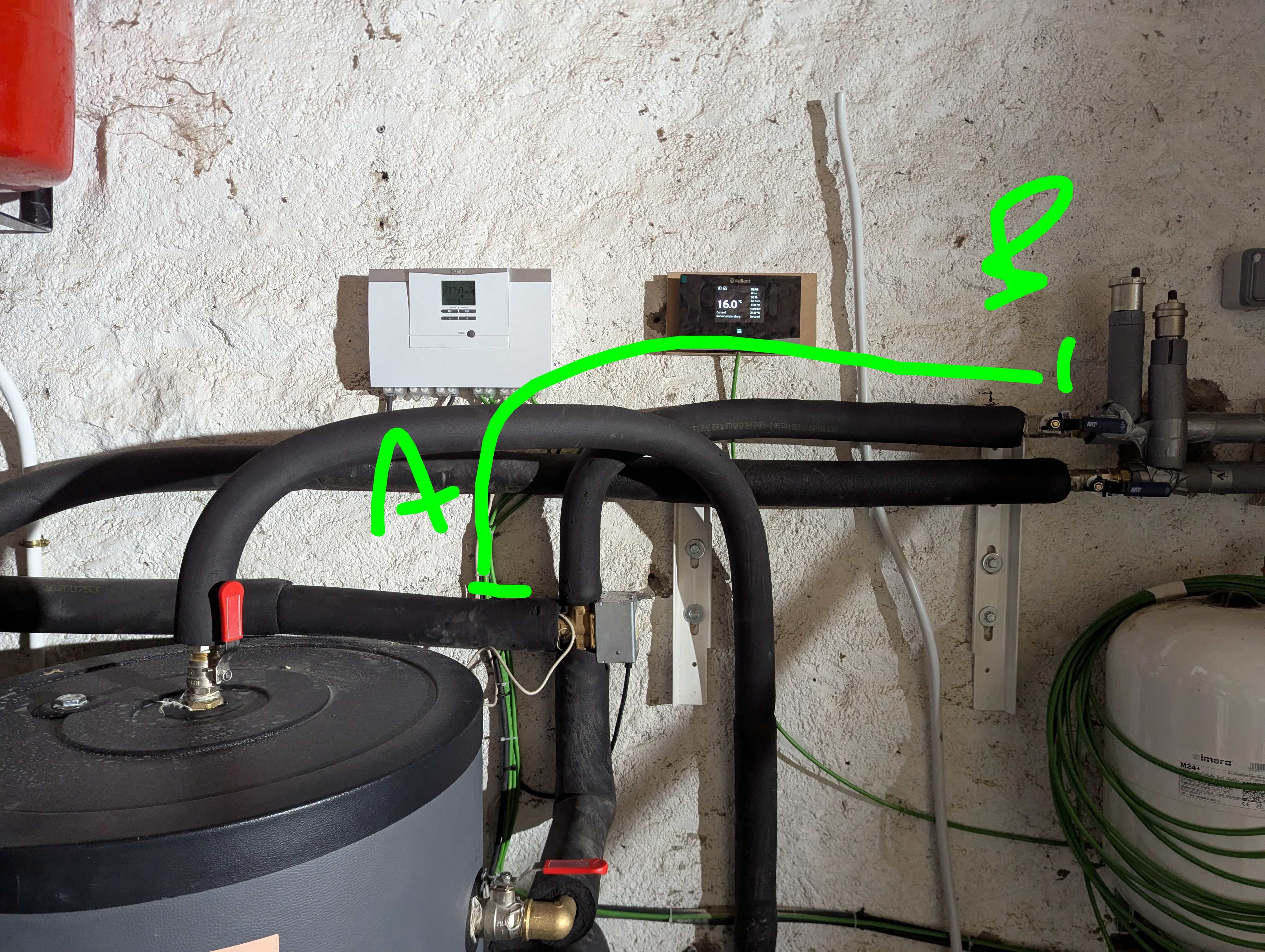
Another question. I noticed the flow return pipe between the 3way valve / volumiser and radiator input is done in 25mm plastic, so 20mm internal. It's about 3m of pipe overall. From A to B. After point B, the copper pipe splits immediately into two 22mm coppers one for upstairs on for down, so it is a restriction. The pipe between diverter is 32mm external. If on DHW cycle we get 2000l/h but 1700l/h heating circuit. Could this short stretch of reduced pipe be reducing flow so much? Before I ask installer to change.

-
The sensor is located near the heat pump in the shade but under a lean too roof, so it's a microclimate. I'll ask the installer to move it to a North wall. And thanks for confirming the tank situation, makes sense. It is actually a good location thinking about it, it's a 200L tank and some family members like scalding huge baths.
-
Also I realise I can reduce the target DHW temp. I should be less worried about temps as actual temps and treat them as a tool to adjust based on if we have enough hot water.
-
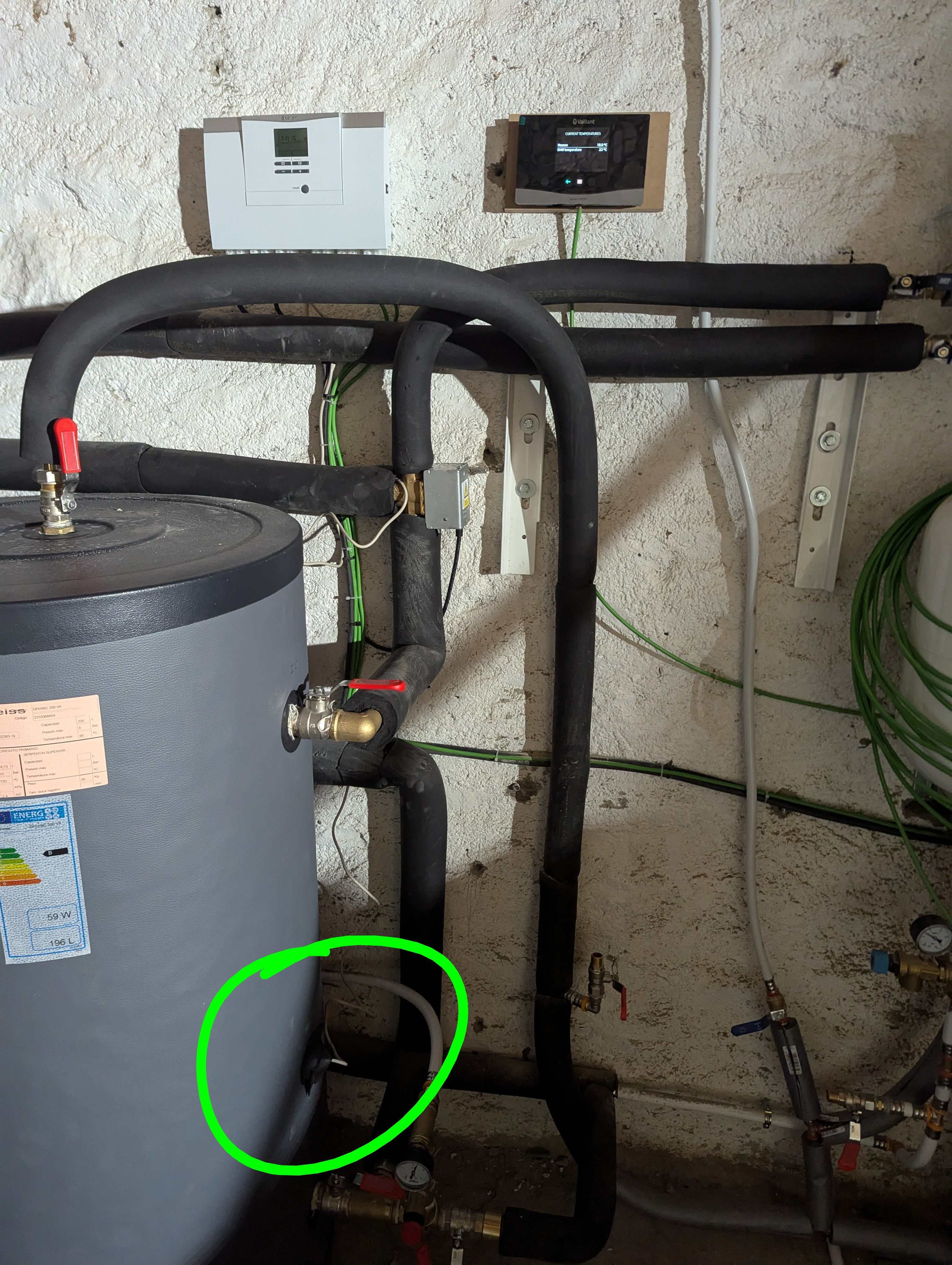
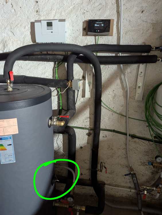
I do seem to have two issue. The exterior temperature sensor seems to have been placed in a microclimate as it's 2C above exterior (real) currently. Also the DHW is reading 23C as the sensor is quite low down, as on photo. Maybe this needs be higher. Or mains water arrives around 12C. The tank isn't 23C as it's coming out nice and hot. Suggestions on this one and where it should be would be helpful. I've set the DHW that it can heat in two windows per day (cheap off peak) so perhaps it's not an issue as it won't be constantly trying to heat. Thanks
-
Great thanks. Perhaps I'm making a deal out of nothing and we won't have any issue being warm with this flow. We will see, it'll turn real cold early November. But February is the worst as solar very low and all thermal mass gone.
-
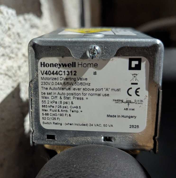
.yes the fixings for plastic pipe are inside the pipe, versus copper which are outside, so each one has a greater effect on flow. It seems the k of that honeywell diverter is 8. So this might be something to look at changing. And check the filter as said. I'll wait and see how the system performs when it's really cold (cold here is -7C solid).
-
Okay thanks for the suggestion. This wouldn't have an effect on heating circuit or overall flow though no?
-
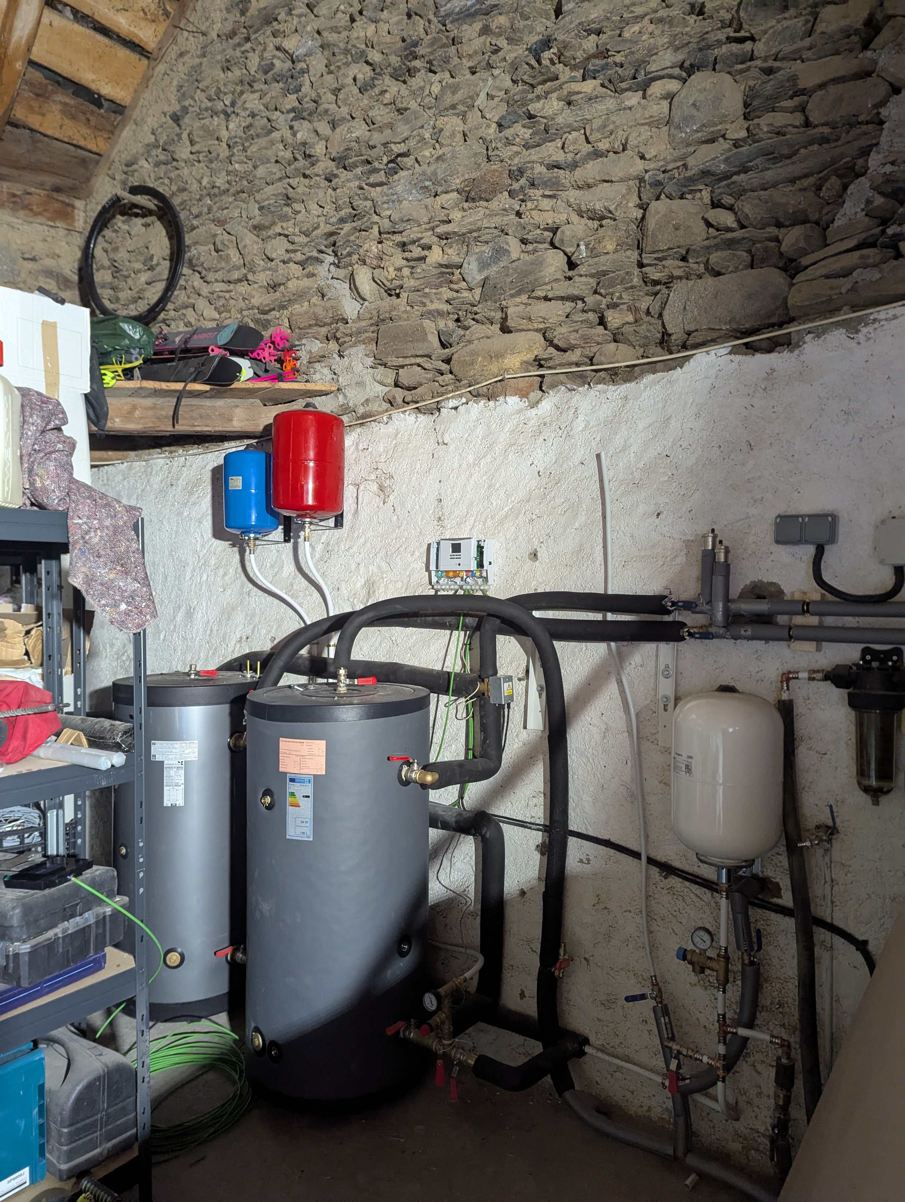
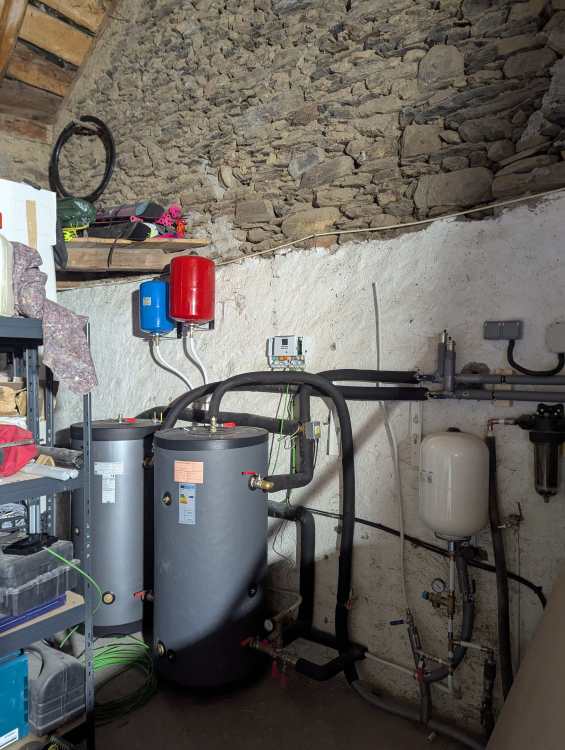
Sorry, I did say rough and I meant it. Good question. One tank is DHW, the other is a 100L volumiser, plumbed on the return leg to the ASHP, radiator pipe in at top of tank, exit to ashp at bottom. DHW right, volumizer left.
-
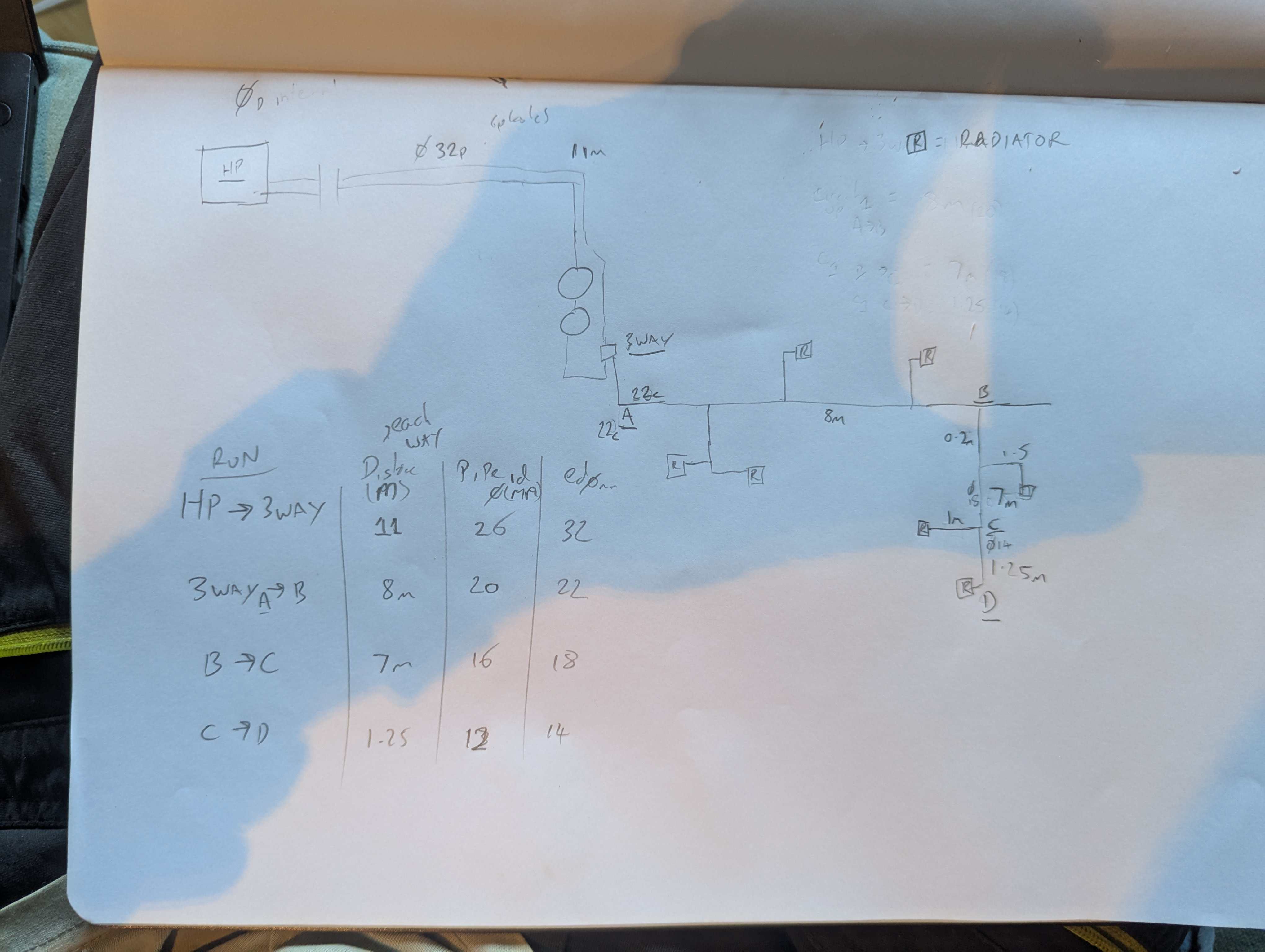
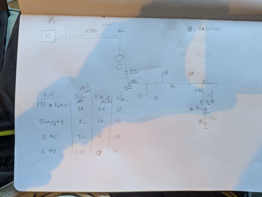
Running the hot water heating, we get 1900l/h. So loose only 200l/h though heating circuit. This is my rough circuit sketch of what I believe to be the index radiator, a point D.
-
No glycol, antifreeze valves.
-
I'm in Spain, but British. The 15kw isn't available in the UK, so I used the manual here. I believe it's the same hardware as the 12 but can just do more power. Maybe something wasn't clear by me. The pipe is 32 od but it's multicapa plastic so 26mm internal - this i what I thought I'd wrong and for a run of 11m should be larger. Thanks I'll check the filter.
-
I drew a plan and did some calcs. I stuck them in chatgpt, with a few prompts and we are both are 35kPa Inc +15% for fittings. Using flow of 1650l/h Can Simone explain delta T, which is assume is at the heat pump. Must it be 5C, or will it be ok at 7C? I'm struggling to find answers to these online. When I asked vaillant they said to aim for flow of 2050. My assumption was that the primary pipe makes a huge difference flow final flow, as it's 11m each way. Thanks
-
That's a good question. I don't know, as it's currently being installed. That's why I'm trying to understand now - if it's acceptable or not. Both before I pay the final bill, and before winter comes and when it's very cold we are not warm.
-
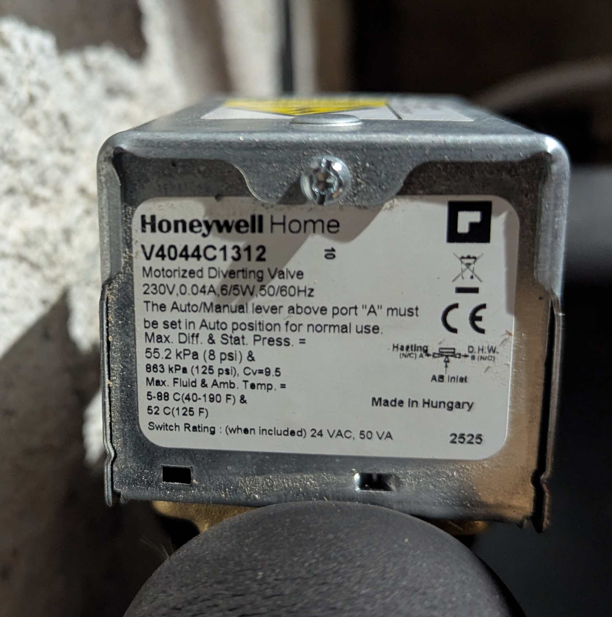
This is the 3 way diverter. Is the cv value the K? And this its 9.5?
-
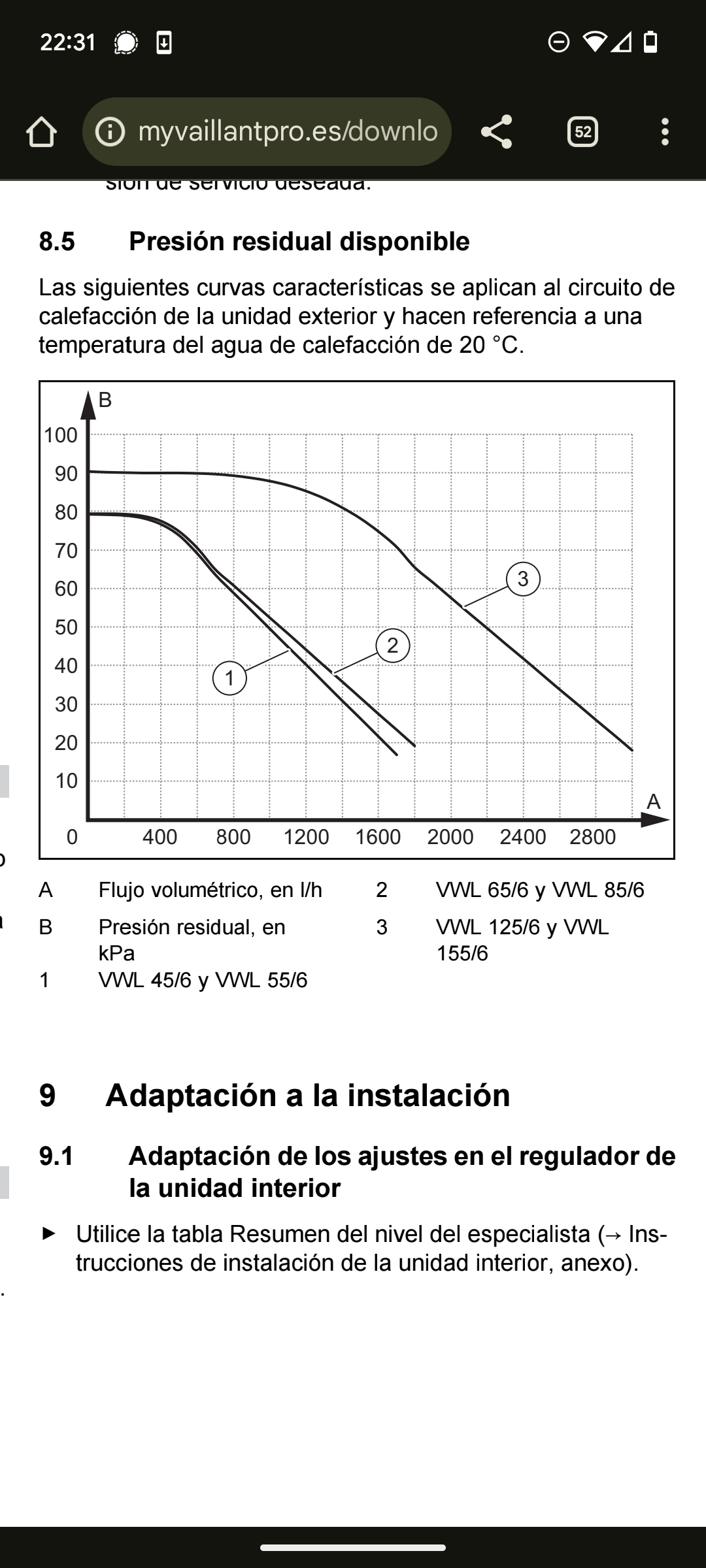
Thanks for the pointers on things to look at, I will get on that. Is 11kPa pressure drop in the primary pipework really nothing? It's 1m head, which could be 0.4m head if it were 32mm internal? Or maybe I'm missing something? (We're talking about only the 22m total primary here, not the rest of the circuit). After the diverter the pipework immediately splits into two circuits of 22mm copper each, which tee off into 15mm tails of about 6 radiators on each circuit. Neither had too bit a head loss as a result of this immediate split flow. All lock shields wide open. Can I please check the location of delta t, and what flow rate I need? Here is pump curve. Number 3, VWL155/6