JohnMartin68
-
Posts
15 -
Joined
-
Last visited
JohnMartin68's Achievements
Member (3/5)
2
Reputation
-
Compression fitting upstream of stopcock
JohnMartin68 replied to JohnMartin68's topic in General Plumbing
SimonD are you referring to the connection with the copper or the plastic? Can't see anything like this on the plastic it looks like it is coupled direct to the elbow? -
Compression fitting upstream of stopcock
JohnMartin68 replied to JohnMartin68's topic in General Plumbing
Deleted see below. -
Compression fitting upstream of stopcock
JohnMartin68 replied to JohnMartin68's topic in General Plumbing
Not really for the indoor plumbing, I want to debottleneck the flow to the outside tap as much as possible for the benefits this may have. Washing, watering and a few other niche uses that aren't so common. I will probably run 22mm to the bath/boiler as well but that's just opportunism rather than any practical benefit. -
Compression fitting upstream of stopcock
JohnMartin68 replied to JohnMartin68's topic in General Plumbing
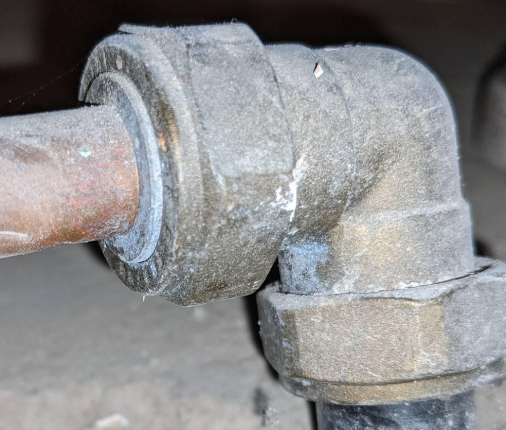
I took a photo from underneath, seems to be the same size as the elbow or a tad smaller. Do you think there's a danger of damaging it when trying to loosen the downstream nut (at the copper, not the plastic)? My technique is to use one spanner around the body of the elbow and one around the hex and squeeze the handles together with one hand if possible. Edit: forgot to say the stopcock is knackered and needs to be moved slightly anyway. But mainly I want to have a 22mm run all the way to the outside tap. It probably isn't going to make much difference if I swage up from 15 to 22 just after this elbow though, so if there's a risk of damaging the plastic I would play it safe.
-
Compression fitting upstream of stopcock
JohnMartin68 replied to JohnMartin68's topic in General Plumbing
External shut off works fine I have used it before. No chance of replacing the plastic I would need to dig up about 50m of pipe and it goes underneath the building. Piping downstream of elbow is all being replaced. -
Compression fitting upstream of stopcock
JohnMartin68 replied to JohnMartin68's topic in General Plumbing
Thanks that reassured me a bit. Piping is probably 1970s and you're correct I really don't want to disturb the plastic connection. Will take extra care not to bend the elbow. -
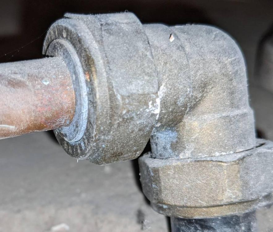
Photo shows a 90 elbow where the incoming mains supply comes up from underground. At the bottom of the photo you can see the incoming mains in black plastic. On the left it reduces to 15mm copper using some sort of bush, going towards the stopcock. Since all the copper needs to be re-routed, I decided I will do some of the main runs (e.g. to outside tap) in 22mm to get a bit of extra flow. Seems simple enough to just remove the bush and replace with 22mm pipe, but are there any pitfalls I should be aware of? For example: - Could the bush be non-removable somehow, in which case I would need to disconnect the elbow at the plastic? - I couldn't quite read the markings on the elbow but looks a bit like 7/8 or something. The marking on the bush flange is definitely 22mm though. Are the metric and imperial interchangeable for compression fittings?
-
The 110mm pipes from the other post can go underneath the slab, but the 50mm ones can't. Long story but they aren't going to the same place.
-
Cheers, what type of mesh would you use? Apologies for ignorance next to no experience using reinforcement.
-
I am going to be laying a floor slab (probably about 125mm thick) that will be more or less bisected twice (trisected?) by two 50mm diameter floor drain pipes. Because of elevation constraints the pipes will need to run horizontally through the actual slab at a gentle gradient, I can't run them underneath the slab. This will introduce lines of weakness in the slab, but.. 1.) Is it worth worrying about as long as the slab is properly supported in all sections? This floor slab doesn't have any structural purpose beyond people and furniture but it will need to support wall hung toilets and a bath. Underneath the slab there is a layer of EPS insulation with a compressive strength of 150 kPa. Intuitively this support is either fit for purpose or it isn't, the slab weaknesses introduced by the drain pipes is neither here nor there as far as the underlayer is concerned. But please correct me otherwise. 2.) What would be the best way to add reinforcements? Something like single layer horizontal grids, maybe each 2 feet wide, running beneath the pipes?
-
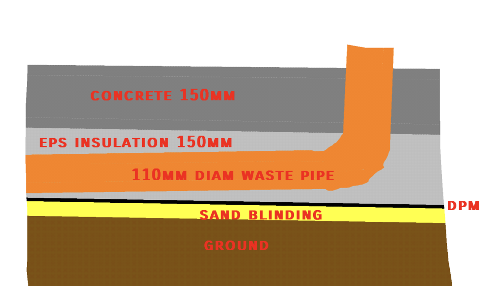
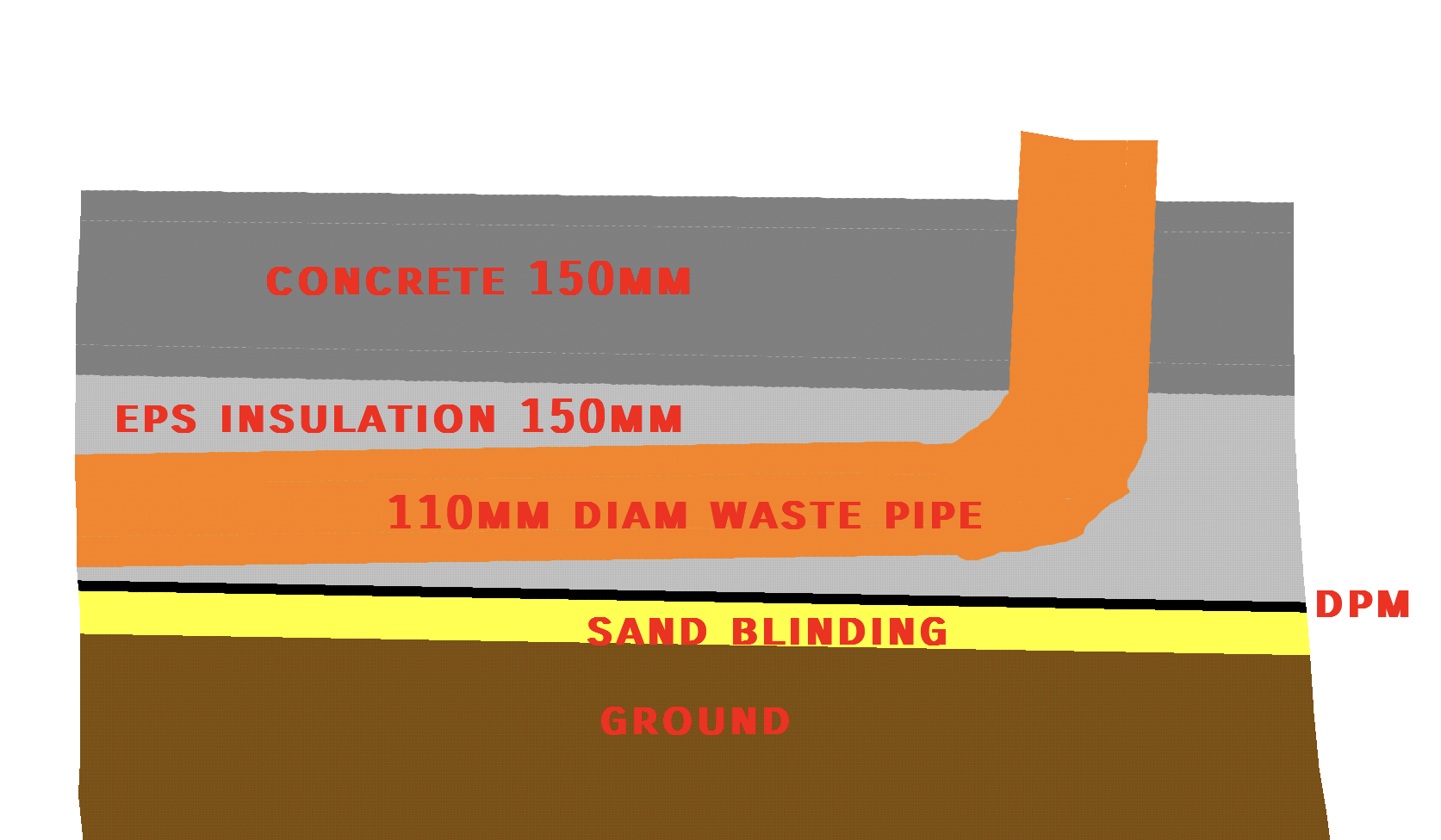
Foul waste through insulation layer
JohnMartin68 replied to JohnMartin68's topic in Waste & Sewerage
Retrofit, there wasn't room for any more without digging below the top of the footing. Single room, small area that needed to be dug up anyway. 150mm vs 300mm won't make a huge difference to total annual running costs even assuming UFH is left on 24/7. The compressive grade is either 100 or 150. It's the premium version which is darker and supposed to have a slightly better U value than standard. -
Foul waste through insulation layer
JohnMartin68 replied to JohnMartin68's topic in Waste & Sewerage
Out of interest what is the reason for insisting on gravel instead of using for example foam? Is it just for compliance with what BC expect to see? For obvious reasons foam wouldn't work in an unlined earth trench but the insulation shouldn't move significantly when its in place. -
Foul waste through insulation layer
JohnMartin68 replied to JohnMartin68's topic in Waste & Sewerage
Not without lowering an unknown but at least 10m length of existing pipe. -
Foul waste through insulation layer
JohnMartin68 replied to JohnMartin68's topic in Waste & Sewerage
Thanks you're probably correct the gravel will provide a bit of insulation. I just wasn't sure if the reasons for using pea gravel to support the pipe were still valid in a channel carved out of EPS instead of a trench dug in the earth. For one thing there must be precaution taken that the gravel won't 'leak' from gaps in the insulation but then if the insulation is laid properly without any voids this shouldn't happen. -
What is the best way to support and protect a 110mm foul waste pipe if it needs to run horizontally through floor insulation? See attached sketch. The elevations cannot be changed for various reasons. I was thinking of cutting a rough channel through the insulation and filling it expanding foam with the pipe in place, instead of pea gravel. Or should it just be pea gravel (this will probably cause heat leakage)?