


Mattso
-
Posts
6 -
Joined
-
Last visited
Mattso's Achievements
New Member (2/5)
0
Reputation
-
Thanks for all the replies, appreciate the input. Only now managed to catch up on the various suggestions. In terms of expense, I'm not too fussed. The cost of fixing the wall, water leak on the floor and broken copper pipes far outweighs the initial cost. Thought splashing out on the Corefix screws was the answer but it wasn't meant to be as straightforward as that. So the first 3 layers of my 1950s wall are plaster on insulated plasterboard (PB + 40mm PR bonded at factory). Beyond that, it's wet plaster, but as mentioned by another poster, it could be 3mm or it could be as much as 20mm. Toggle clips are designed for hollow walls and dot and dab, so I don't know if the toggles will expand the way they should. So to summarise, the options I'd consider are: -9mm drill bit into bricks using 120 Corefix (possibly too short but I could cut off the top and push them into the hole by a few cm) -fill the hole in the brick with resin or quick set concrete, push the corefix plug in, wait for it to set and screw the screw in as intended. -masonry screws, but would have to be at least 100mm long if not longer and might cut into the PB + Insulation under weight -Coach screws maybe. Ideally I'd use the 5 different 10mm holes I've already made into the wall. So they'd have to be 10mm x 100mm min in dimensions. Cheers.
-
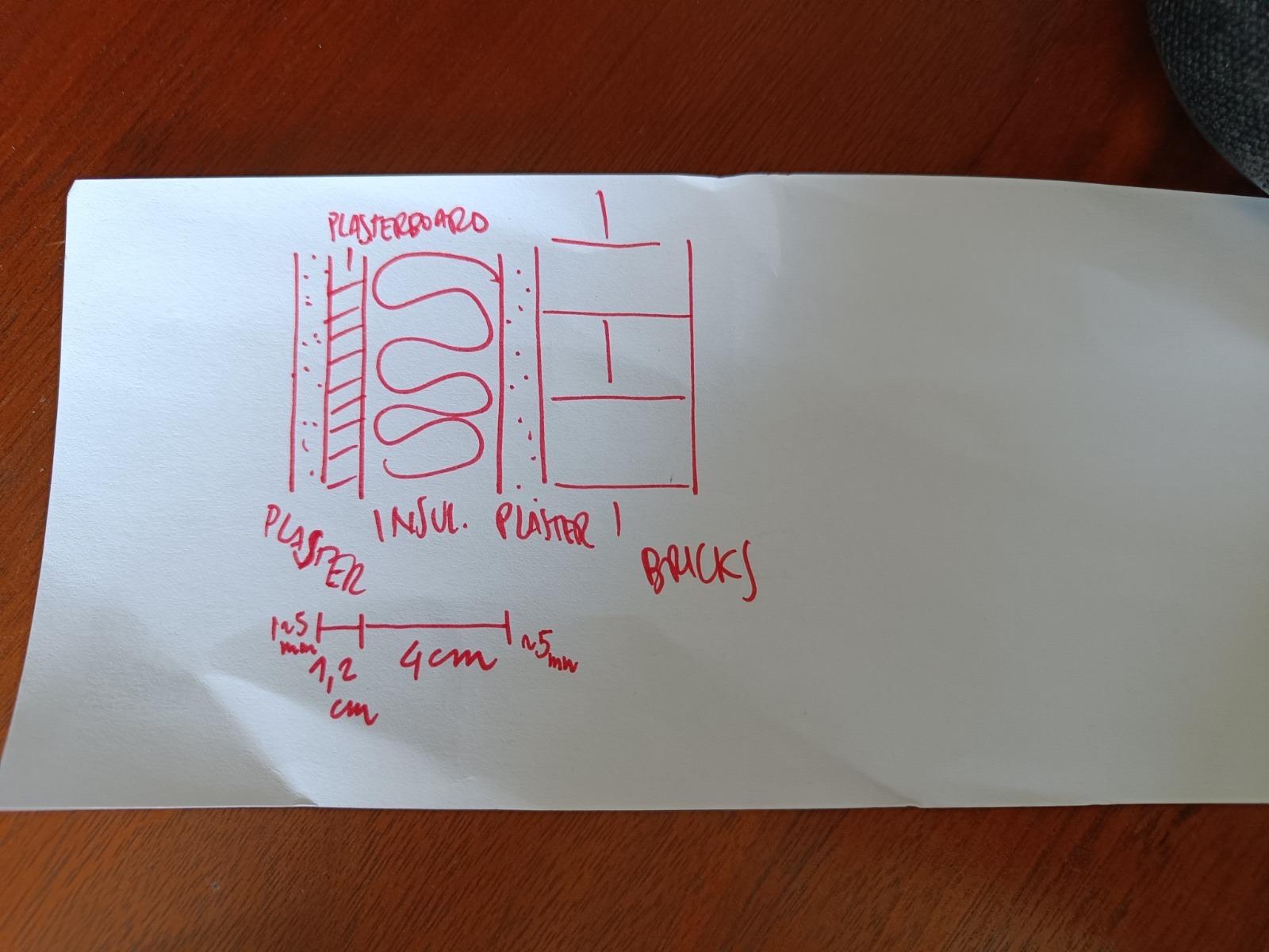
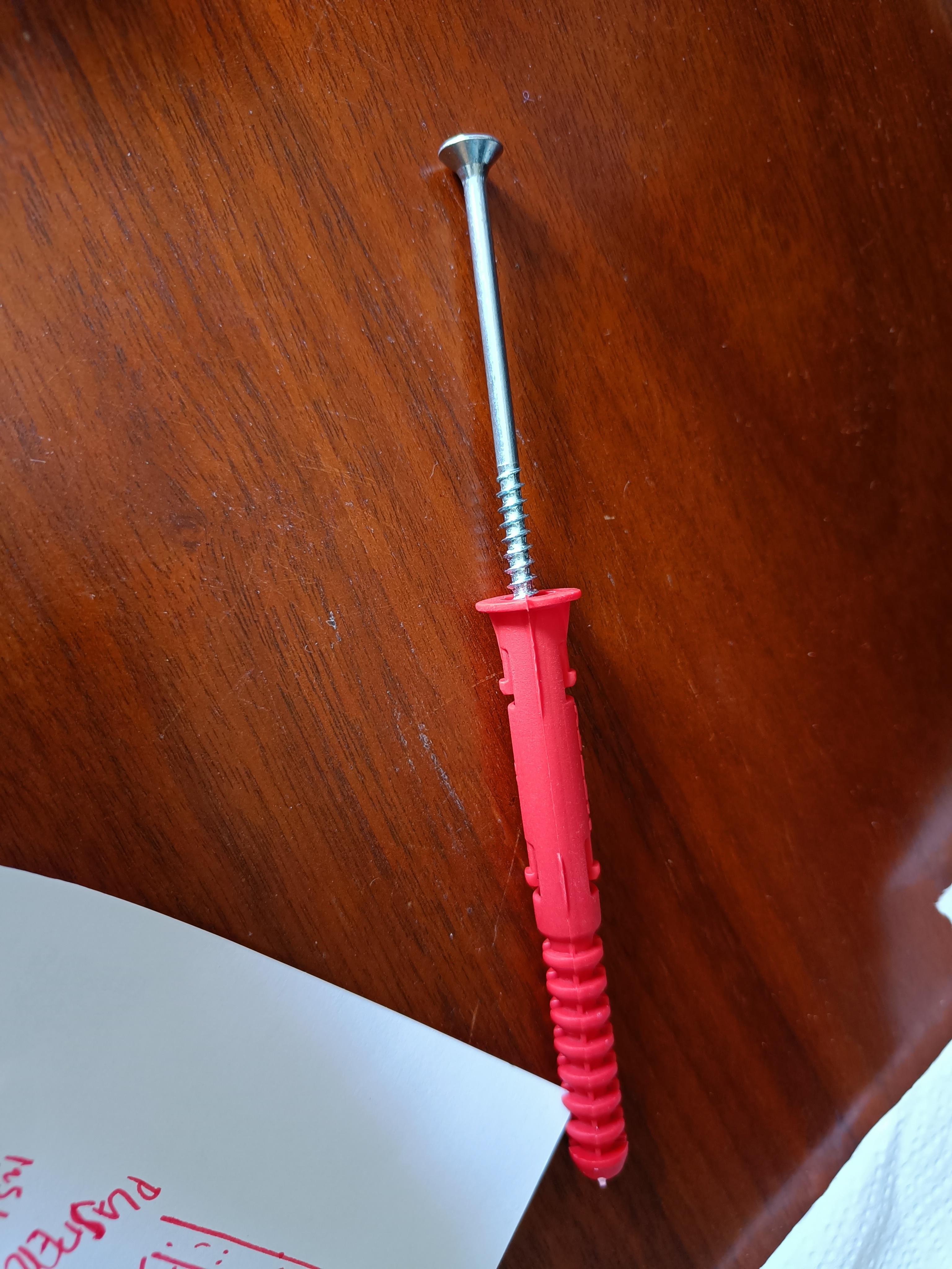
Hello. After plenty of resaerch I decided to go for Corefix 120 screws to attach 8 screws for 4 radiator brackets. The wall is, from inside to outside: plaster -> plasterboard -> 40mm celotex PIR -> old plaster -> External brick wall. Made the appropriate holes with the recommended dirll bit of 10mm diameter. When attaching the screws and gently screwing them into the core & plug, some bite. Others just end up spinning while the plug stays in place. So the screw just chews into the plug and when i pull the whole the screw away from the wall, the entire plug and bracket just comes away from the wall. So the plug is not doing what it should. I had the suspicion that the plug was too short, so I also cut the head of the plug off and pushed the plug & core 30-50mm inside the hole. Was hoping more of the plug would be in the brick. The result was equally unsuccessful. The only other idea I have is to use a smaller drill bit to make a smaller hole in the brick, in order to squeeze the plug and force the screw to bit. Other than that I have no clue how I will get this radiator installed in the wall. Any suggestions are welcome, short of questioning the use of internal insulation 🙂 Below is an image of the schematic of the wall. Thank you


-
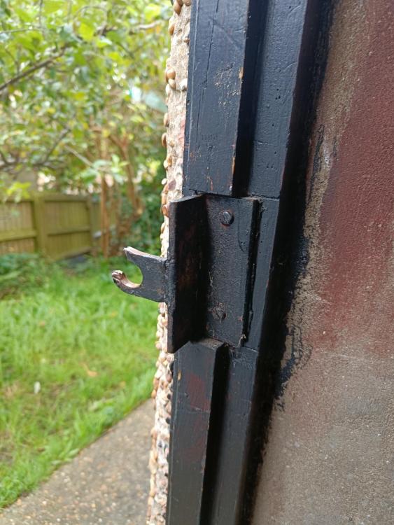
Been burgled over the weekend. Someone forced entry into the side door leading underneath the house and took a bunch of stuff. Thought the space was safe but obviously wasn't. Now I need to secure the space and improve security. I'm aware that there are other factors such as lighting and cameras maybe but my questions is about the strength of the door and lock. I'm attaching several images of what the door looks like now. Shall I get a metalworker to remake and beef up the piece that's been snapped off (how do you call that round eyelet?) or maybe rethink the entire door? Many thanks in advance for any suggestions. Mattia
.thumb.jpeg.a37d1c8f37f3b8da67e67bae4e268298.jpeg)
.thumb.jpeg.e4ca9c24f0ff7f799ab09c21f0b0eceb.jpeg)
.thumb.jpeg.0d5bfca5ae45c40898982e6dd1bf0261.jpeg)
.thumb.jpeg.90c8a46ff3e1071a575f374eee6235cd.jpeg)
-
I'm still trying to work out if I can get away with not taping the warm side of the PIR. If taping the cold side (underside) I guess the concern is that moist air makes its way through the gaps in the PIR (it won't go through the PIR) and get trapped by the aluminium tape, condensing on the taped timber. Any condensation on the underside of the PIR/ timber isn't a concern as the undercroft/ crawl space is well ventilated
-
Thanks @jayc89. From what I gather, the PIR + aluminium tape should make any further membranes redundant as it's considered a fairly airtight combo anyways. In my specific case, I'd like to avoid lifting the floorboards to add 'stuff' on the warm side of the insulation.
-
Hello, I just came across this forum and I'm sure I'll be spending many hours on here in the weeks to come. I'll be insulating a suspended ground floor using PIR. As I have decent headroom underneath most of the floor, I'd like to insulate from below rather than lift all the floorboards: cut PIR to size, fit between joists, attach some sort of batten, spray foam any gaps. As floor for the rooms, I'll be keeping the original floorboards, and will be filling the gaps between the boards with pine slivers and glue before sanding everything down. I'll make sure any potential air gaps will be addressed. The question (1): Is there any point of or recommendation for using aluminium tape on the underside of the joists, to create an air and vapour-tight barrier? Ideally, I'd put the aluminium tape on the joists on the warm (room) side of the insulation, in order to allow the joists to get the benefit of underfloor ventilation. Bonus question: This probably depends on the answers to the previous question; I'll be removing some 50mm Celotex from between some joists where my predecessor did a so-so job. Any point in cutting those boards down to liberally cover the underside of the exposed joist, in order to provide additional insulation? This, as the aluminium tape, would interfere with the ventilation of the timber joist, therefore maybe not recommend. Many thanks, any thoughts are welcome.
.jpeg.f5387c5698e342fb72b529ec2a4f2d06.jpeg)
.jpeg.1a3d5cc7c46076e1ebe34d5bb003a704.jpeg)
.jpeg.ee83c43a9c9267a60dd5a21d5603412f.jpeg)
.jpeg.778460b39c1f17d8080e103820b3681d.jpeg)
