Sumo
-
Posts
19 -
Joined
-
Last visited
Everything posted by Sumo
-
Sorry, should explain in regards to the zone statement, our 3-port manifold is for two rooms, so two stats, I keep the lowest heat loss room with the stat off and just call from the colder room, to avoid over calling.
-
Thank you for all your efforts, John. I will spend some time digesting and altering them to see the changes. My head is elsewhere due to a crisis at home, so I probably need more time to learn some more. The 4l/min used by the ufh only, from the ashp flow, highlights why the ashp struggles to modulate to the low demand, especially as ours does Not have a auto-bypass around the ufh manifold. If the ufh was left as two zones, then a demand of 2l/min would be making the ashp run, crazy to design a system that can call for power yet only need to use 10% of the capacity. Thanks again.
-
With loss I was meaning that you have had to heat your water upto 54.5 when you could say heat it to 44.5, is that not a potential 20% saving? With mine, it was realising that the 9l/min through the loops, was only using say 4.5l of water from the ashp. The 9l through the loops always has to be more than the water returned to the ashp, for seperation?(sorry in advance if i am a, wrong novice). Seen as the ashp needs a flow of 20l/min minimum, if we just ran the ufh we would short cycle. So to improve cop I have balanced the whole house (7 double rads and 70m sq of ufh) as one, all operating on there check valves alone, so no tmv or trv or zone actuators. The largest heat loss room on the ufh loops dictates the ashp run time. I have made it so well balanced that the ashp permenantly modulates and never cycles on or off, no choking through lack of demand and no aggressive ramping up/short cycling through too much demand and the return temp not been reached. It is always running untill the coldest room is happy. My bill is down 30% along with a warmer house. My ashp targets 46c, water que's at the manifold entrance at 50c and leaves at 41c, the 3 loops now run at 37 return and 41c flow. Three of my radiators have a flow of 46 and return of 41 and four are around 39/34. I still have not got around to re doing the manifold to run without mixing, the flow and return need swapping over, a new pump and an auto bypass valve to handle the unused 11l/min, are at the ready, meaning hopefully I can run the ufh on its own occasionaly and use 9l/min of un mixed 46c water, though I have not done it as I am worried I will mess it up.
-
Hello John Caroll. I hope you are well. I am the poster/owner of that uhf loop. Not sure this will help. I have one question for you, to see if we can improve your efficency? Can your floor surfaces tolerate more than the 30 centigrade that your ufh TMV is set at? The closer your tmv is to your boiler flow, the less the loss, John Cantor did a youtube on it. As you say you need your boiler return at a minium of 40, it would make sense to target an ufh return of at least 40. Also that way you are reducing the loss through mixing at the manifold. Can your boiler target lower than 59, or is that needed for elsewhere.
-
Thank you JohnMo, that sounds like an easy solution. I may have to treat the uf system to a new grundfos upsm3 along with the pipe stat.
-
Hello Temp. Maybe wasted was the wrong word for me to use. I can now understand the heat transfer between the circuits, so there is no loss it is transfered heat, it just seems very inefficient to have an ASHP targetting 48 c when the secondary achieves 36-41 at best. I think it maybe best to forget/remove the mixing section and swap the flow and return primarys around and then put the pump on the primary flow? I know there are saftey concerns when removing the mixer, from a double fault occuring,ie, the ashp goes awol and heats at 60 and not 48, and then the room stats also fail, so allowing constant heating, also that room stat failure would overide the 5 degree setback which limits the heating for 17 hours, and then an eldery relative falls unattend onto the floor and gets burned. It is possible but I could not guess the probability of those three events happening at once.
-
Thank you John Carroll. I now understand a lot more and it is good to put a name to the tapstat. So my primary-ashp circuit is flowing across the manifold with a delta T of a) at x) flow rate but my secondary ufh circuit has a smaller delta T of b) and faster flow y) through the manifold. It is like the heat is being taken from one circuit to the other, as opposed to being given to the circuit. When pople have mentioned a figure of eight I could not conceptualize the flow's but if I see it as two slightly overlaping circles, with one trying to feed from the other it makes sense. On the floor covering/flow temp debate, we have stone tiles and carpet on concrete, would I be right in thinking they could take a 48 degree flow if I could achieve it? If so, I am wondering if a different manifold setup with more control on the minimisation of the mixing could be more efficient. I am wanting to avoid short cycling, which we often have, as when combined with the defrost cycles it means we are not using much of the economy 7 power for heating. It is more cost effective to run with a higher flow temp for a short period than a lower rate for longer when the electric is 3 times cheaper.
-
Thank you for your patience JohnMo. I get it now. Once I got my head around the fact that it was actually meant to be this way. Uponor have recently been selling them, see below.
-
Up.
-
Thank you Temp, you have summed it up well. My ASHP is only having 45.5% of 9l/min of water used. So, with a theoretical flow of 15l/min for the whole system flow rate, in theory we are wasting 2/5th's plus 55.5% of 3/5th's. A very inefficent setup when you want to block heat your slab only on economy 7.
-
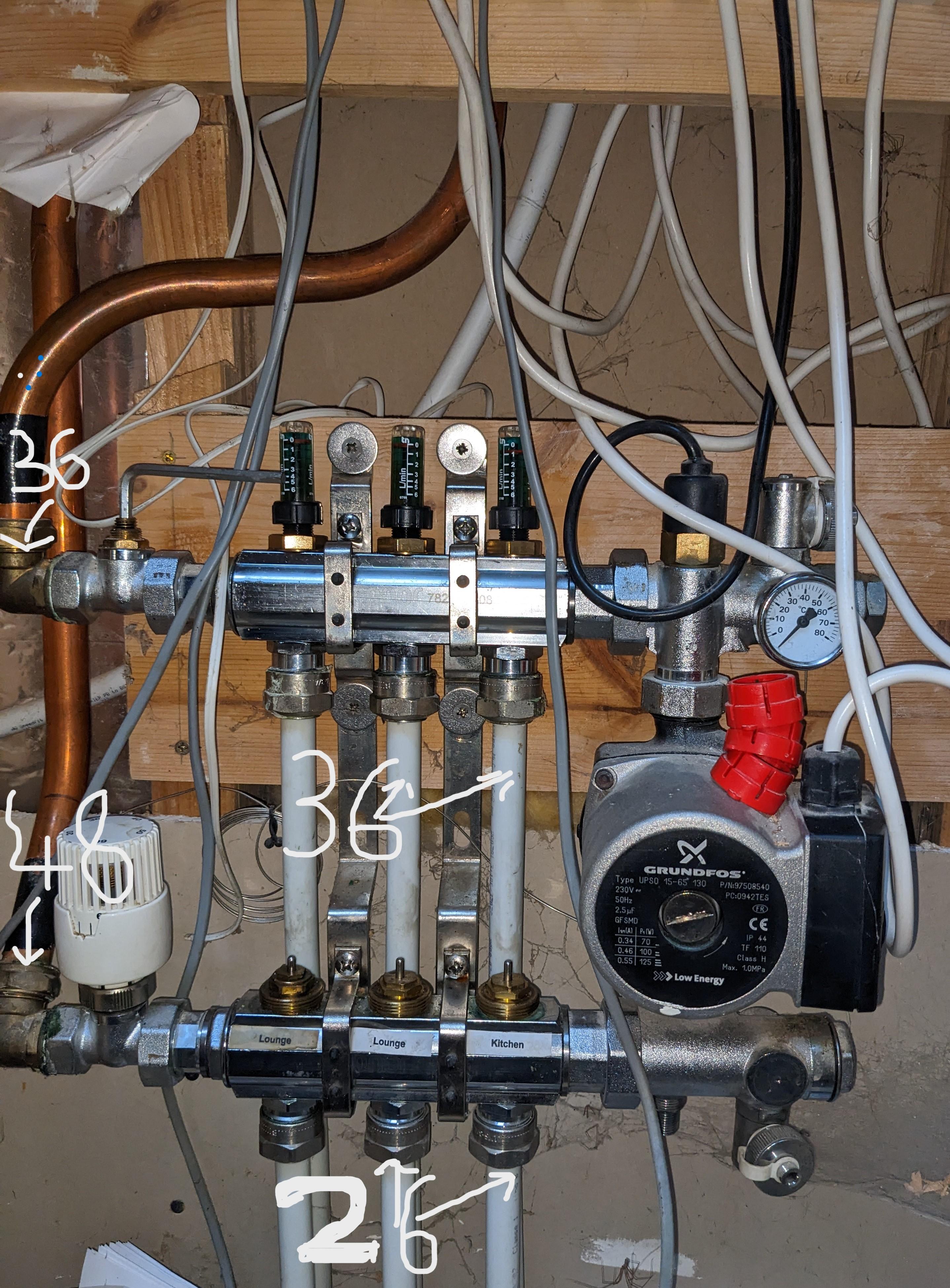
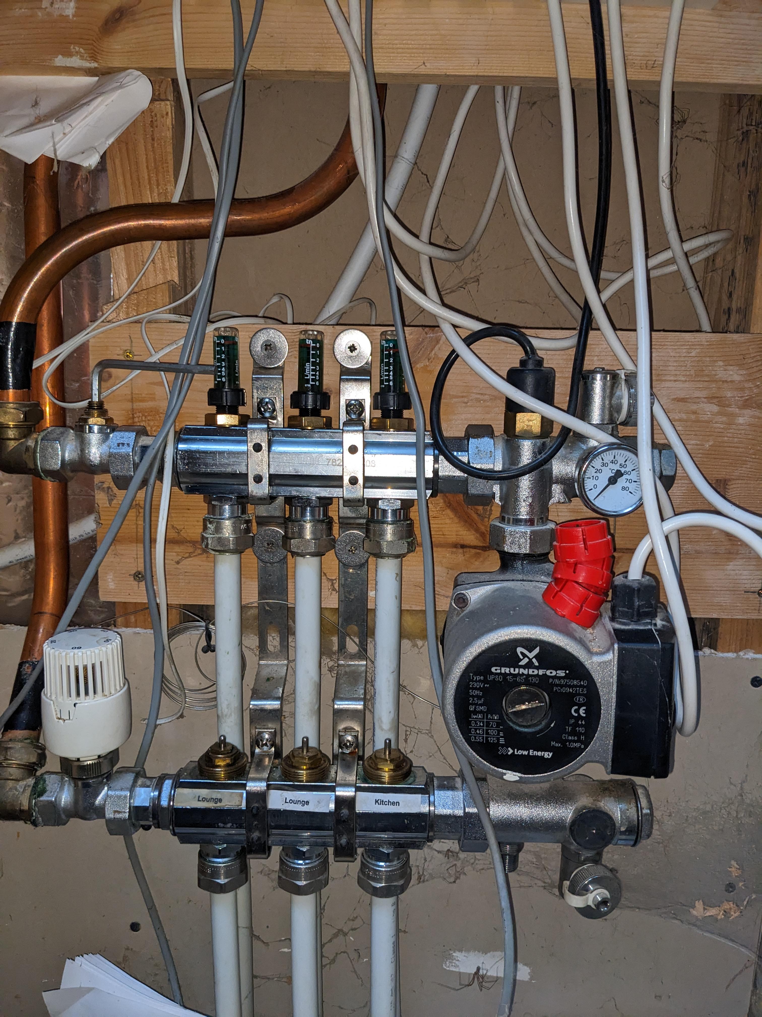
Hello John, the pump arrow is pointing Upwards. So, the flow is entering via the lower "return manifold" where it is being "mixed" with the return's from the ufh loops. Then up through the pump, over the flow valves and out through the upper "flow manifold". Complete nightmare. Also the TMV is not a direct mixer valve, it is a single bored piece, with no direct mixing facility. The mixing being permenant, via the suction on the ufh return loops as mentioned, mixing the 48 celsius input with the 26 degree uf loop return's.
-
Hello Temp, thanks for joining in. Yes, I had spotted the equation with in the numbers and I can see the theory. However I cant understand why any blending is needed. It is a bit like a false positive signal. Surely with the pump to the right , it is pulling water from the manifold in flow point, and the assumed lower return plastic pipes, this is then sent up towards the return flow and the assumed in flow floor loop. My question is, would all the water not take the path of least resistance, through the big copper return pipe, that has two additional pumps pulling on it, rather than through the loops. It is as though the water through the loop is only there as it is been dragged away from the return by the mixing pump, as opposed to being sent and circulated through the system.
-
I think I know how and why mixers work, they seperate and mix flow and return dependant on target to protect the floor when you are running a system at a higher target temp to feed the rads than the ufh needs. My Thermostatic valve is set wide open above 60 degrees, so with a flow in of 48 and return of 36, no mixing is needed or should be happening? I checked the TV is opening and closing by listening to the flow changes/feeling resistance and also the pump tone changes. I plan on maybe removing the tv blender and just having the pump or a new grunfos model3, on pressure setting, at the flow entry. I just want to block heat my slab on economy 7, with no restrictions. How can you say it is working efficentley when actual flow temperature through the underfloor is a max of 36 with a delta 10 for a 26 return, yet the ashp is heating at a target of 48 and is prone to cycling off every seven minutes when it overshoots its target. If I set the ashp to a target of 37, I get 25 in to the loops, so it is not as though the blender is specificaly targeting the 36 I have now. I think I should be getting say 46.5 in through the loop with the ashp at 48, with a delta between 5 and 7 across the floor, so returning to the ashp with a delta 10 max.
-
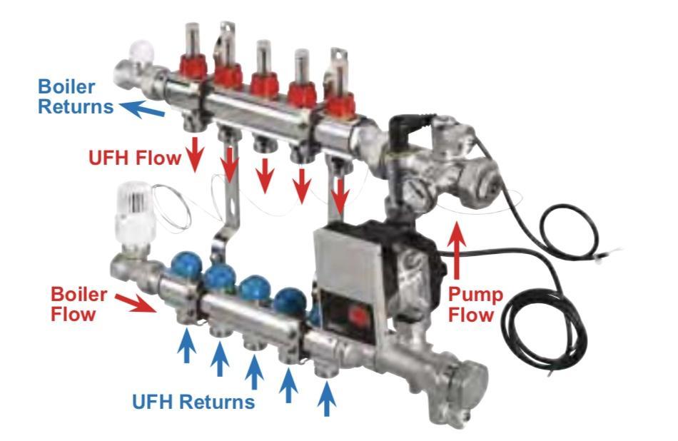
Sorry, I still do not understand. If my flow temp in is 48 but my flow through the loop is 36, where has the 12 degrees c gone? And if my return flow into the manifold is 26, how does the return flow out of the manifold reach 36 suddenly? Also, not wanting to be difficult but how can we trust your picture when it is clearly labled in a contradictory manor. If you look at your picture, on the right hand side, it says "manifold(flow) and on the left it says "flow to underfloor loops" pointing to the top section. With "manifold(return)" on the right and "flow from underfloor loops" written underneath, pointing at the bottom section of the manifold. Then, if you look at the detail you are relying on, which is written to the left, it states "boiler return" from the top section (already twice discribed as the flow) and for the bottom section it is "boiler flow"(already twice discribed as the return) So the picture makes no sense. Sorry John, I have two heating engineers look over the system and neither has picked up on this as a fault, so I have to look closley for the solution.
-
Hello, I am fairly convinced I have a manifold flow direction issue. I thank JohnMo and ProDave for there contributions in my introduce yourself post. I have a fifteen year old ashp-UFH, manifold system that I can not believe has been plumbed in REVERSE and thus has been costing my old parents a fortune all this time. Also confused how a Mitsubishi accredited engineer could comission it as fit, but that is not the issue. I know a manifold can be plumbed into the left side for flow and return whilst having a circulating/mixer pump on the right side, that would not be an issue. It is the fact that the FLOW is entering at the bottom and the RETURN is comming from the top, see below for the numbers, the flow should be through the top. When I disable the mixer pump I get zero flow/min through the meters(are they one-way flow meters? thus hitting the flow meters from the wrong side) dispite having two additional circulation pumps and the ashp pump working. With the mixer pump I get 1.5 to 3l/min depending on pump speed, though as you can see from the numbers below , it is not going in the right direction. It is like it is working against itself. I removed the actuators and opened up the temperature /mixer valve plus opened the manual ball valve whilst trying to fathom this, the mixing pump runs on wall stat demand? The infra red heat gun figures are the key. Any clarity to say yes you are right, swap the flow and return around , would be helpfull.

-
I do agree Dave, that the mixing pump can be on the right side, however as we do not need a mixing system to protect the floor I would like to use it as purely a circulating pump on the inlet.
-
Hello Dave, thanks for the reply. My manifold is an uponor 782??08. Yes, I have come across that image before. I found it confused? They point to the flow and return to/from the boiler in the same orientation as mine but then when you look at there flow and return to/from the ufh they are marked as the reverse directions to there input flows, so I think they have misslabellled the diagram? I considered this for a while and assumed a clever network of pipes hidden in the manifold, but no, they are just open voids.
-
Thanks for the reply Johnmo. I always run the rads seperately, with both on at the same time nothing gets hot. But yes I run both at 47 to try to block heat the slab on eco7. The ASHP is set to 47, it was set to 51 but I noticed it having to work very hard over 47 to get to 51 and then it would overshoot. With just the UFH on the rads get a flow of upto 25 degrees through them, with the highest temps coming on the rads at the far end of the loop, so backwards. The best delta I have had at the ASHP is 13, mostly 15, despite trying every pump combination to get better, the flow meters all reads 3 on the manifold. Two Grundfoss pumps, one either side of ashp. I am sure the manifold is the problem, as you and all the internet says flow in the top. I just want lots of opinons saying, yes the manifold must plumbed wrong. Thanks.
-
Hello, I am a looking for advice for my DIY brain before I contact a plumber. Last winter I took over the responsability for a Zubadan 8kw ASHP connected to seven double rads and a three loop UFH manifold. Having noticed the ASHP short cycle, every 5-10 minutes with a 3 minute shutdown I decided to investigate as a novice. I wont go through all the symptoms I spent months fathoming over in this post, I will start one in the plumbing section, but here I will cut to what I think is the issue. The Manifold I think is installed wrong???? Pictures below. I bought an infra red heat sensor to figure this out. So, I think the flow and return copper pipe is the wrong way around! and the pump is not helping. Onto the numbers, the lower copper to the trv reads in centigrade at 48, the upper pipe from the manual valve reads 36! So to me, the flow is coming in the bottom and not through the top flow valves, as it should? To add to this, the flow temps in the lower plastic pipes is 25/26 and in the upper plastic pipes it reads 36. I want to swap the flow and return and reposition the pump into the flow pipe, I will block heat the concrete slab on economy seven, with no mixer valve needed and the zones all open, so as one circuit on a timer and wall stats with set back. Any thoughts for my sanity are welcome.