
Leaderboard


Popular Content
Showing content with the highest reputation on 05/30/22 in all areas
-
Some valid points above and I will make some of my own, but you can do what you want. If you think it will really help, crack on, but be aware, my thoughts are as follows: There will be some benefits to having a single main contractor do all of it. In all honesty they should be fairly quick at demolishing, I assume, a house and can coordinate future requirements with the demo. The benefits are to the onward journey, for example, utility disconnection can be handled now and at reconnection by one, with machines on site demo and found digging can be combined with a single machine on site, certain things can be left and certain things must go. I am making a fair number of assumptions there but I am sure you can see some of the benefits.2 points
-
Why not replace the whole things will slim line led fittings they are about 10mm thick. Possibly a bead of sealant to stop drafts. Example of light fittings, I mean https://www.toolstation.com/led-slim-round-panel-light/p71575?store=LJ&utm_source=googleshopping&utm_medium=feed&utm_campaign=googleshoppingfeed&mkwid=_dm&pcrid=558038224734&pkw=&pmt=&gclid=Cj0KCQjw1tGUBhDXARIsAIJx01kit9HU4Z30HFIGvtfHDQNDi6WQvOSsinvm_jkeYgKNOTkA2ocQ7ZQaAjvaEALw_wcB&gclsrc=aw.ds2 points
-
Small section with the same cross section should be ok. If you worried about noise, insulate around the changes in cross section shape. If it's the same cross section the velocity will not change. Noise is generally flow induced by velocity. You should look up the pressure drop caused by the transition pieces to ensure they are low pressure drop.2 points
-
I had a few spare minutes on this lovely sunny Sunday evening and decided to spend it writing up a blog post for our basement UFH install and screed. We have a 250mm reinforced concrete slab sitting on top of 200mm EPS300 in the basement. The slab wasn’t very flat and so we decided to use a cement based liquid screed to give us a nice level base for our finished flooring. So we put down 25mm of PIR to level things out and also to allow the UFH pipes to be stapled to. I did some quick maths and I figured out that it was cheaper to use the 25mm PIR and UFH pipe staples than to use pipe clips fastened to the slab and a thicker layer of liquid screed and so an order was placed with our BM and it was delivered and fitted by my lovely wife and me. We found this is a pretty easy task to be honest and only found we had to put a small bit of sand blinding to level a couple of dips in one room. In the rest of the basement the PIR just took the bumps of the slab out. We taped the joints and foamed around the edges for a belt and braces approach even though there was a DPM going on top. Next came the DPM layer. We found this a bit of a pain to do! Not hard but trying to smooth it out and keep it square so that a constant amount was taken up the walls was just fiddly. In the end we got the laser level out and set it about 150mm above screed finished level and then used that to ensure we had enough DPM up the walls. Then we had to tape it to the walls but soon found that standard gaffa didn’t stick to the concrete walls nor the dense concrete blocks! We painted the concrete with a PVA mixture and that helped a lot for that but just didn’t work on the concrete blocks at all. Off to Google and this awesome forum and I eventually found Gorilla Tape which sticks well to concrete blocks and we were off and running! Following this we laid the UFH pipes. This was a job we actually really enjoyed. It was very satisfying creating those wonderful spiral shapes. We made some spacers and I was laying the pipe according to the layout designed by Wunda and my wife was walking behind with the stapler ‘kerchunking’ down the staples as we went. At the end it looked so good we were sad to think all our hard work would be covered up and never to be seen again. This was my first time running UFH pipes and also my first manifold fitting and I was very happy with how the manifold turned out. I filled the pipes with water and the pressure gauge showed that there were no leaks. That and the fact there water wasn’t pissing out anywhere! With the liquid screed booked in we needed to get a move on and get everything finished off and ready. The last stretch was to fit the temperature probes, perimeter expansion strip and create the expansion joints for crack mitigation at the doorways. Thanks to advice from this forum’s users I ran the temperature probes in UFH pipe with the end crimped down so as to not allow screed in just in case they need replacing in the future. I got the expansion strip from uHeat on eBay. It came with a plastic skirt and adhesive already attached so it was a real breeze to fit. Not much more to say about that The final thing was crack mitigation strips for between the doorways. After speaking to the screeder I decided to use 5.5mm plywood board. It was an inexpensive and simple solution. I was asked to cut them to size but leave them to the side of the doorways and the screeders would add them as they went around. Obviously I had to put them in place first to ensure I got the sizes right! So here are photos of our basement ready for the liquid screeders. On the day of the screed they turned up early before the screed lorry to setup their pump and check on my prep work. They said it was exemplary and that I wouldn’t believe the state of the prep work of some of the jobs they turned up to! They had absolutely nothing to do to the prep work which made them happy and made me happy that all our hard work was worth it. They put down their little tripod level thingies and waited for the screed to turn up. Once it did it was really quick work and very impressive. If it wasn’t for the fact that they ordered 6.4m3 of screed but the company only sent 6m3 they’d have been done in a few hours but, as it was, they ended up having to wait a good 2 or 3 hours for the last little bit of screed to turn up. They were not happy as, in the end, they had to spend the whole day here when they could’ve been on to the next job. But, at the end of the day we had a wonderfully flat looking basement floor. And 48hrs later we were walking on it. 🙂 All in all very happy with the whole process and I will be getting these guys back in to do our ground floor screed. thanks for reading.1 point
-
One for the MF experts, I've used all the timber I had on site for studs, spurred on by others I'm curious about MF and fancy giving it a try. I've got a section that needs framing but the wall runs across a sloping ceiling. Can it be done with MF, or best stick to timber for a task like this? The issue I'd have is with the top Channel, how to have it pointing down, rather than pointing out into the landing... is it a case of bending the U track, or cut a section of timber with an angle that matches the slope then attach the U track to this?
 1 point
 -
Hope this helps a bit. Just watch the timber thickness.. as in an 89 depth it is often 38 mm thick as opposed to 45mm thick that you get with grade C16/ 24 95 x 45. Please ignore the branding, it's just a snippet I have in one of my data sheets, makes for easy reading though.
 1 point
 -
Okay, I’m convinced! 😄 Thanks Joe1 point
-
As Russell, but this must be official. As MarkC, there are proper transition pieces in plastic. There will be turbulence but should be ok. How long is the duct? Flexi ducting will cause more flow resistance than the change in section, so use smooth pipe instead of bendy ducting and it will all work better.1 point
-
I always preferred separate stop beads, it allows you to be accurate with the doors it case either the frame or door is not completely square!. Fit the door with hinges and catch then fit the stop beads leaving a 1 mm gap for paint or varnish 🤷♂️1 point
-
Tanking brush or roller applied will work great on blockwork1 point
-
You could try, as a bit of a bodge, setting the GU10 lamp into the base with some silicone (all of which will withstand high temps for this application - it won't melt or burn, but use silicone). Yes it means they will take a bit to get them out but a little pry with a screwdriver and it should achieve what you want. Good news is your draughty ceiling void will help prolong the life of these lamps!1 point
-
I think they will still leak air. The lamp will be a tighter fit into those, but not airtight. Technically only a fire rated downlight will achieve what you want. You can get some decent fire rated GU10 down lights - but if you can stretch to the more expensive option I would high recommend it.1 point
-
No. Broccoli are flower heads before they flower. The rest are even earlier when harvested. I thought you were netting the beans.1 point
-
Install those Aurora or Luceco ones and you will not have to change a bulb all built in and fully sealed, also a little more efficient and better optics and lumen output than a GU10 LED lamp (which have little inbuild LED power supplies (drivers) which get hot and fail.1 point
-
@ReedRichards Just had a thought while I was up in the loft tidying. Too high a temperature is not really a problem as your system design can just use a temperature blending valve. So really the things to look at if seriously considering a Sunamp are the kWh price and the size they take up. You can always parallel them up for extra storage.1 point
-
Replace them with fire rated LED downlights. Something like the Aurora Enlite E8 or the Luceco F-type will work on a budget.1 point
-
Can you get the structural engineer to stick a couple of 80mm holes in the steel.1 point
-
As above, plus transition should be as long and smooth as possible especially when changing from rectangular back to circular relative to air flow. If the transition is short vortices and turbulence can occur and these will affect noise and efficiency.1 point
-
No idea. Ask their technical department or the technical sales at one of their agents. From my understanding, Sunamp lost the plot a few years back when they got involved with a large marketing company. @Andrew Bissell - Sunamp may still look on here, or not.1 point
-
Everything Simpson is over priced. Can you just replace these with a simple wind post. 75mm box section. I bet the reason they specifically said Simpson is they have the calculations readily available and don’t need to do their own.1 point
-
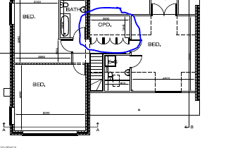
Most of the cladding looks to be in good order, as does the roof. Leave well enough alone I say. What are you planning on doing with the windows/doors? One area that might merit some thought would be the bottom run of cladding. It looks like it is suffering from some splashback from rainwater ( red looped areas) . Normally cladding wouldn't start 150-200mm above the ground to prevent this. A simple solution might be to cut the concrete along the blue line maybe up to 300-400mm back from the wall, with one of these. You could break it by hand but it wouldn't be as neat. Then dig out 300mm deep and backfill with 100-150mm of gravel. This should be enough to ensure the timber stays dry. What is your plan for the electrics? If the internal ply hasn't rotted with the poly/paint sandwich by now it's not going to. Get some airtightness tape and tape all the joints in the plywood and tape the doors and windows to the ply. Tape the ply to the roof and floor making a perfectly airtight box. This is more important than insulation in creating a stable internal environment. Very easy to DIY, just takes care. For the walls I'd use 63mm CLS set back from the wall by 38mm @600 c/c. Any smaller timber will be too bendy to get a nice wall finish. You can use a 38*63mm CLS timber on its side screwed through the ply tot he studs at the top ( and bottom if required) to create this setback . This will create a 100mm ish (63mm+38mm) space to fill with 600mm rockwool batts or similar. Also the gap behind the studs will give you a nice thermal break and leave a gap for the electric cables etc. Then cover with 15mm plasterboard. If you glue the two layers or OSB together with all joints well staggered and stick down the Amtico too it'll work fine. I'm not an expert but I can't see any issues. You'll need to get your floor insulation dead flat first however. If the floor of your shed is undulating use a straight edge and some sand/cement mix or tile adhesive to fill any low spots. Put down your insulation and the OSB on top. make sure to leave a few mm for the OSB to expand at the edge. For ventilation I'd use something like this and a trickle vent in the opposite wall . OR if you want to splash out something like this, For heating I think in a small space, the heat of the printers and humans will make even a cheap air2air heat pump unnecessary. A simple plug in rad will be fine. Sorry for the scattered post. Hope it makes sense.
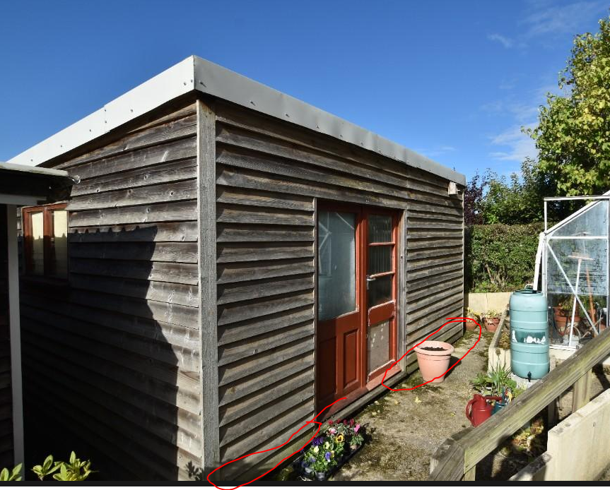
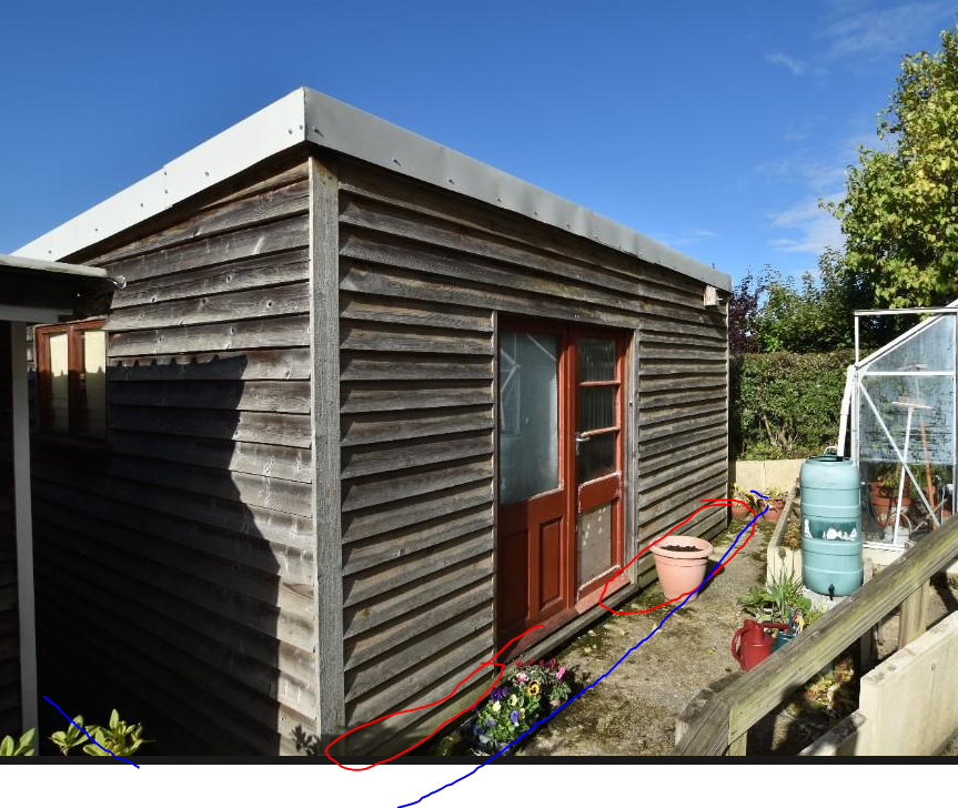


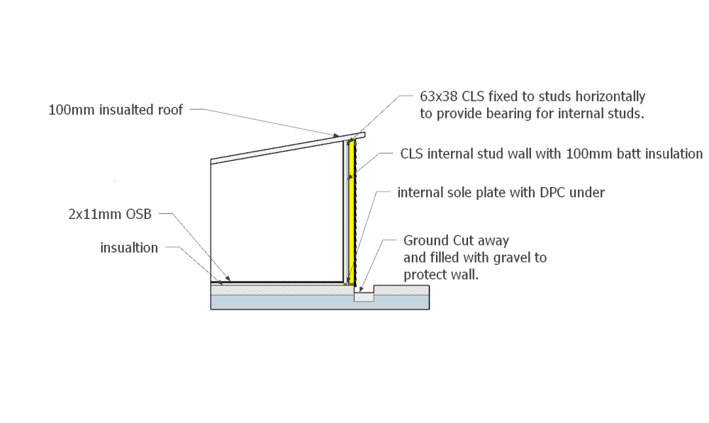 1 point
 -
If they get to the pollination stage, theyre far to far gone. We eat the unopened flower buds essentially1 point
-
CE have had a website update and are now also offering an R32 based unit that has EVI (Enhanced Vapour Injection) - which, from my understanding, offers improved COP at lower ambient air temperatures. I'm heading to the Installer Show at the NEC next month to look at some equipment in person and will update once I've learnt more.1 point
-
usually the grate on the drain has a hole for the pipe to poke through. my 1980's built house is the same. it would be worth re-pointing your blown out brickwork where the pipe exits your wall1 point
-
Do it Australian style. I had multiple groups of this as I built in a semi cyclonic area, wind load was horrendous. Ive never seen anything built like it over here. So so basically they make a racking wall using threaded rod and plywood. Bottom plate is fixed to concrete raft with an anchor bolt that has a female thread facing upwards. This bolt has a length of 12mm threaded rod that goes up through any noggins and up through the top two head plates. Theses are fitted every 1200 mm along the wall, directly inline with the size of plywood sheets. The ply is fitted with full head nails, nailed every 150mmm. In effect it creates a 1200 x 2.4 box. Start at the corners and work up to reveals. Full sheets on all corners and reveals. If your interested i will will do a little sketch. All materials readily available of the shelf.1 point
-
Double OSB plus these Wow! Yes strong walls also add to the holding down as well as racking but I find it hard to believe they are needed. from a design point of view they are convenient as they have a tested and proven capacity but in the past braces and ties have served us well.1 point
-
Yes. Our compressor and tank was checked, every year I think. The small portable one was ok, think it was under 15 lt.1 point
-
If I was buying battery kit from China I'd stick to lithium iron phosphate (LiFePO4 AKA LFP) batteries as they are significantly safer than regular lithium ion (NMC, NCA). The economics tend to drive the manufacturers more than safety factors and LFP's are more forgiving to design for.1 point
-
I wouldn't be so sure. Pressure vessels aren't everlasting and at the very least are likely to require statutory inspection under the PVD/PED , if not exchange and/or nondestructive or hydraulic test...1 point
-
Thank you Mr Punter. I have a build over agreement with Severn Trent Water.1 point
-
It may be better to run the vent to the back through the bathroom. You may need a build over agreement with the water company for the sewer.1 point
-
I think we would need to see the plans to make sense of that? Are you suggesting your fan will vent into a narrow gap between your house and next door? Why not just route it to the back of the extension and out the back wall?1 point
-
Over how long? An hour, day, week, month, year, decade?1 point
-
We have a heating strategy of keeping our house at the same temperature 24 × 7 (accepting the ±½°C ripple that I mentioned above), though one side effect of having a super-insulated house is that even in winter the house only cools by around 1°C / day if the heating is off. But the same thermal design process needs to be applied even if you live in a conventional low-insulation leaking house: If you are using UFH as your primary heating source then if your house looses X kWh / per day heat externally, then your UFH heating strategy must supply the same X kWh to keep overall heat balance. That (~7 × Δtemp × Area) W is a good rough estimate of how much heat the slab can throw into the room environment, so the more heat you need to input then the higher the Δtemp needs to be, though once this gets up to 10°C then the floor starts to get pretty uncomfortable, and you really need to worry about potential hot spots under in-contact furniture, etc. Higher rates of temp rise can cause heat stress in the slab which isn't a good thing. This is why IMO you want to insulate where practical and cost-effective and try to remove external air leaks and use MVHR as this will dramatically reduce your overall heat requirements. A more standard higher O/P slab will benefit from a TMV mixer and buffer tank design, though because the water circulating in the slab is a lot cooler than that in a radiator installation, UFH installations are a far better fit to ASHP installations. Last thing to remember if you are going for a non-constant Time-of-day profile, is the issue of time lag. With a 100mm+ slab (especially if the UFH runs are placed at the base of this) then the heat has to propagate through the say 80mm of concrete before the surface is at temperature and the floor starts to radiate heat into the room. This means for example if you want the house to be warm when you come home at 6pm, say, then you might need to turn the UFH on at 2 or 3pm and likewise turn it off at 9pm, say.1 point
-
Get the tray. Ours was nearly 10mm longer and wider than stated.1 point
-
I using a 160l thermal store as a buffer, standard coil rubbish when using low temperature flows. I have just added a large 40 plate heat exchanger as well as the coil.1 point
-
However you need to make sure a coil will cope, mine didn’t and had to convert it to non coil 🤔1 point
-
Err, nope! A trap is formed when the pipe rises again, after the basin has discharged, 'trapping' water eg blocking the pipe. Yours both show continuous falls so are fine, however option 1 would be the quietest method. You hear much more nose / sound from water changing direction and from significant drops before the invert. FYI I have started wrapping soil and waste pipes with Kilmat / other sound deadening mat as a solution to banning the higher frequency noise, plus as much acoustic rockwool insulation as is practicable for the lower. It is imperative that the pipe runs do NOT contact the metal frame as that will be like an amplifier.1 point
-
Have you seen his site ?? i can fully understand the need.0 points


This leaderboard is set to London/GMT+01:00