
Leaderboard


Popular Content
Showing content with the highest reputation on 05/28/22 in all areas
-
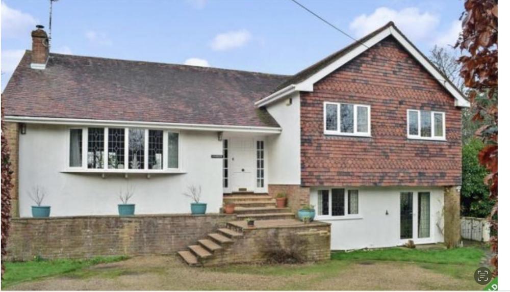
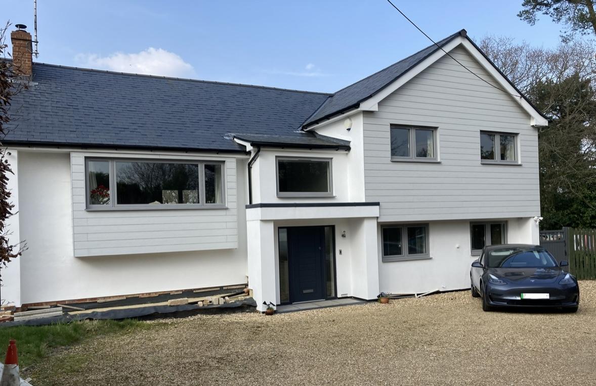
Time for an update! Here is how it looks now. Just the lower wall to finish off on the left hand side. Apart from the roof tiling, all DIY by myself and the Mrs. Before:
 5 points
 -
Different takes on approach here from Peter and Charlie. BH is about say buying your first house/ flat, doing it up, then..maybe self building or just sitting back and saying I did that once and that suits me, innovation, the excitement and that deep personal reward you get, feeling of achievement. I think Charlie and Peter to my mind have identified part of the problem. Charlie mentions new SE's coming in not knowing about the building regs in detail, it's a valid point.. on a social level it could be defined as the division of labour, see for example Adam Smith.. The Wealth of Nations for a bit of background. In summary we all have become more specialised in what we do as the population has grown and now we are arguing the toss about a few quid between Architects and SEs etc. We used to draw on paper, now we use a computer.. it's just a tool. I can spend a day, sometimes more on cad just working through a detail that will last for 50 - 100 years more I hope! Before I could go through a wad of paper. Folks on BH.. it's the thinking time that counts not how fast you can move a mouse. @CharlieKLPbut the same can can be applied to young Architect's and other young designers. It's not their fault that they maybe have less intuition about how to realise their designs economically so that they will actually get built. My advise to the folk on BH is this. Rather than look to save everything you can on professional fees find the right fit for you. You need to work to find the right person for you, they are there and they will save you money in the long run. Bear this in mind. A good tradesperson will cost you £250.00 per day at least. Say £1250 a week. A good designer only needs to save you one weeks labour on say an extension and they have washed their face, never mind any material savings.. and here we are splitting hairs on how fast you can draw in CAD or look up the building regs to check something! Don't get hung up on a few hundred quid on design fees and how fast someone may be on cad. The test is this. Can my designer deliver what I want and save me more than I'm paying them any extra in fees compared with just getting a bog standard "off the internet" design.3 points
-
I the only thing I have been told is that they won’t discharge my surface water drainage condition until they have suitable mitigation. So what’s frustrating is my surface water cannot get to a watercourse and to the broads. Basically they don’t have a clue what to do about any of it, so they are stalling1 point
-
@pocster Nah they all live down in the dungeon. The 48V on PoE is useful though as 5V sex toys tend to be a bit meh.1 point
-
Toolstation do them on 3 day delivery as do Victoria Plum. When do you need it ..?1 point
-
Just to Update this thread, and close it off. Site investigations prove that this proposed drain is an original Rubble (field Drain) drain. that runs to the coastal cliffs It was explained to me that before these fields were farmed and flatter, this would have been a natural watercourse for run off water, over many years farmers would plough the fields and fill these watercourses with stones from the ploughing, and eventually over many many years flatten the field with the run off water now running through the rubble underground. My site has bed rock at varying levels from 250mm to 500mm from the surface, in general the ground falls North to south to the sea - 500m approx. My proposal to SEPA was to run my Waste Treatment outlet through a 50M smooth perforated pipe Rubble drain , then discharge to this rubble drain. I have given them my best estimate off discharge to the sea, this came from talking with the locals / and some walking around the cliff edge.. Ultimately SEPA have accepted my proposal, and I now have a certificate to discharge.1 point
-
Moisture proof board I am assuming ..? And why OSB and PB when a single skin of cement board would be quicker and cheaper ..?1 point
-
Plasterboard or cement board ..? The latter is a pig to adjust. Tray will be about 2-4mm different in size - usually less than dimensions quoted.1 point
-
@SuperPav, Mesh selection is really a choice for your SE or whoever did your slab design and it is driven by that. Using the mesh as a placement framework for the UFH piping is really a secondary bonus and shouldn't impact on mesh selection. As to slab heating, there are broadly two strategies at the extreme: Dump heat into the slab at a steady rate so that the slab remains at a slight Δt above room temp. Here it will radiate ~ 7 ×Δt × A W into the interior. If this matches the net heat loss of the house, then your house will stay at the set temperature. Calculate your total kWh house losses for the coming day, and for a given input heating rate this give a total heating time. Just dump this into the slab in one or more "chunks", and accept that this will result in a slight ripple (say under 1°C) on your internal temperature. We have a passive house and have adopted the latter as this was easier to implement, in terms of kit required, ease of control, and simplicity leading to maintenance risks and reduction. The thermal dynamics here is a different Q entirely and one where I feel more qualified to answer on. I did my slab design back in 2015, and I was one of the first ones on this forum to go with a UFH solution which went against the prevailing wisdom of including a buffer tank. I decided to use a 3 kW Willis heater to heat the slab directly and use it as the thermal store for the heat. I needed to do some modelling of the slab for me to be comfortable with this solution and to ensure that it's thermal performance during the heating cycle was well within sensible limits, before finalising on this implementation. Luckily my professional background give me some experience of doing this type of modelling, but the main challenge was one of producing a model of the correct simplicity yet enough detail for the exercise to be meaningful. I have previously documented this in my blog posts and and specifically in my thread, Modelling the "Chunk" Heating of a Passive Slab written in late 2016. For the modelling, I didn't want to get into the complexities of CUDA compute engines and CFD libraries, so to keep the math and computation simple enough to be computable in Fortran on a single core (which is what I used back in the 1980s when I did this sort modelling for a living), I approximated the slab heated by one UFH loop as a (radially symmetric) concrete pipe some 0.120m in diameter and 100m long with a 15mm heating pipe running down its centre and with water circulating through it and heated by a 1 kW element before return. This allowed me to use a simple radial approximation for the Fourier heat equation and to solve over time for the (r, l, t) coordinates over time and the length of the pipe. (See this post for more details.) OK, it's a model and an approximate one at that because the actual heat flow through the pipe is not radially symmetric as the area around the heating pipe is insulated below, radiating to the air above, and adjacent to another. Even so, this did allow me to investigate the overall varying heating characteristics over time and both along and across the concrete. This was good enough to confirm that a "Willis direct into slab" approach would work fine for me. I subsequently instrumented the actual implementation with lots of DS18B20 digital thermometers which have been continuously logging now for ~5 years, and the slab behaves as predicted. This can be summarised by more simple and intuitive approximation. The slab surrounding a single pipe heating loop can be thought of a (folded) long box of concrete that is insulated below, radiating to the air above and with similar boxes on either side (since these are being heated by a return run at a similar flow temperature). The UFH pipe flow is dumps ~1kW (in my case) heat along the centre of this long box, and so the water cools as it flows along the pipe. The overall Δt is largely dictated by the water flow rate which in turn depends on the pump head, flow resistance, etc. In my case this was the biggest difference between the model and actual implementation, as I went with a slower flow rate than my modelled 1 m/s, in order to keep the circulation noise to a minimum. (The UFH is in a services cupboard off or G/F toilet and I don't like to hear the pump noise when I am taking a dump). So as the long "box" heats you get a standard radial heat flow curve where the circulating water in the middle is maybe 5°C hotter than the surface during heating period, with maybe a 2-3°C drop along the 100m run length. As the heat is dumped into the slab, it slowly but steadily heats up over the heating period, say by 5°C or so over a 7hr heating window. Certainly if you walk over the slab at the end of a heating cycle in bare feet (as we do), you can notice the 1-2 °C variation across the floor between the flow and return legs of the UFH runs and any gaps in UFH coverage. Pretty much as soon as the heating stops, the heat from the warm spots spreads so the feel becomes more uniform (as the heat only needs to flow ~50mm or so through the concrete). We heat our slab overnight, so by midnight the slab might be ½-1 °C below room temperature. In the morning after heating it might be 4°C above room temp, and it is now radiating ~28 W/m2 into the environment. This rate will fall during the day as the slab cools, leading (in our case) to a ~1°C ripple on the overall air temperature. The integrated heat dump from the slab must match the overall house losses, so the colder it is the more we need to heat the slab; and the warmer, the less. I hope this makes sense.1 point
-
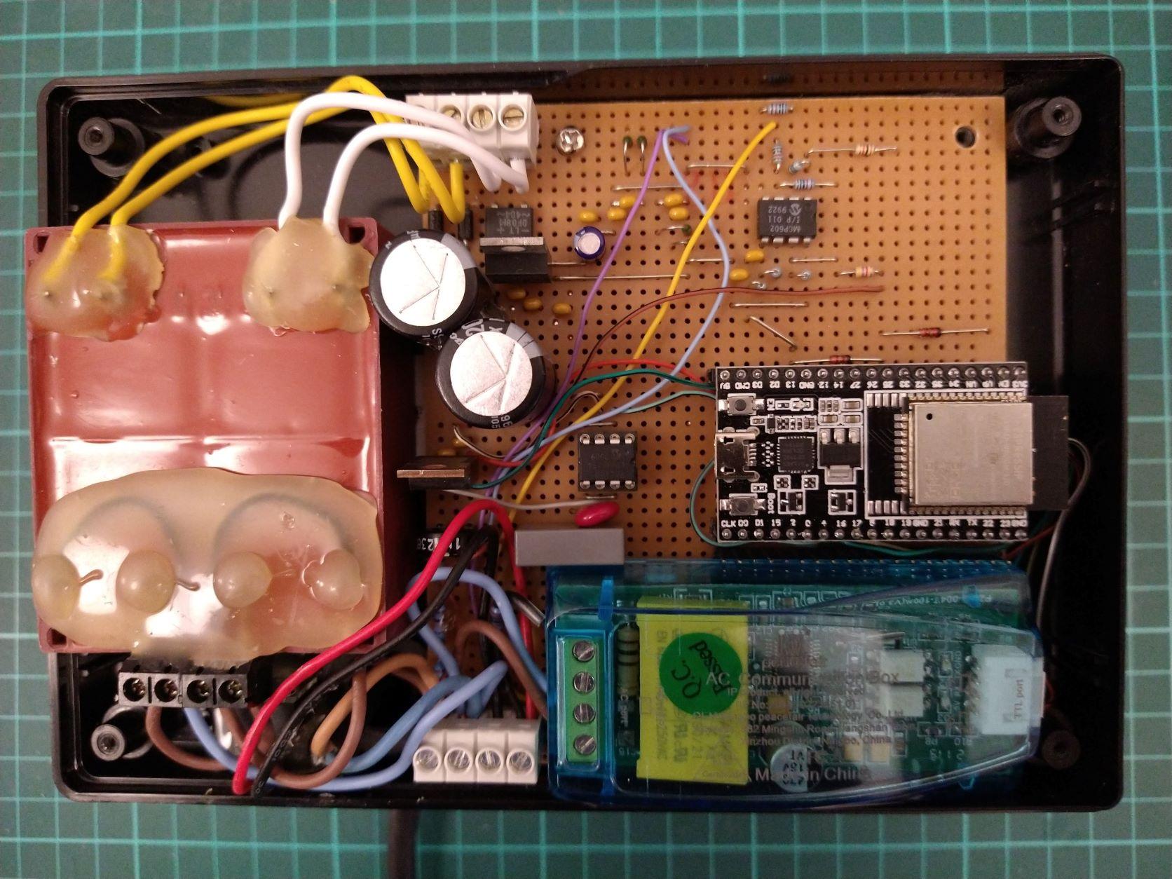
I find it quite fascinating. The project is a nice intersection between the full stack of EE disciplines. I think I'm covering all the territory by having a LAN-centric design which gives me good visualisation and control and a chance to flex a bit of analogue design muscle because the DIY projects I've seen tend to just poke a resistor biased transformer output straight into an ADC input. I'm making full use of the air-gap afforded by the WiFi connection and 'riding' the mains voltage directly. The mains is also being used as a low-latency communications channel with the power switch which is, I think, quite novel. The prototype unit in development. Even though the circuit potentials are referenced to the mains neutral, I'm still using a split secondary transformer to derive separate DC voltage supplies for the analogue and digital sections. The PZEM power measurement unit is bottom right. I'm only using it to confirm my results and may remove it eventually. I'm sharing the same Current Transformer that came with it. Just to the left of the ESP32 module is an 8-pin DIL mosfet gate driver that makes an excellent 120kHz mains modulator (coupled with a 0.1uF X2 rated capacitor). Not much else other than a couple of linear regulators and a dual OP-Amp for signal conditioning.
 1 point
 -
I think anyone doing a knock down and rebuild should perhaps propose the knock down as mitigation on the grounds the overall project will be neutral. Apply for the condition to be discharged and appeal if it isn't. If they refuse to process it Appeal for non determination. If you don't get a response to the application to discharge there is a "deemed consent" procedure. Will be important to follow the timescales allowed. Others with conditions.. There are a lot of rules the planners must follow when imposing conditions. Some make conditions unenforceable, such as those that cannot be met or require you to use third party land. If the problem can only be solved by the water companies I suspect you could argue that what the planners want you to do is unenforceable. https://www.gov.uk/guidance/use-of-planning-conditions Perhaps a group of you could get together and hire a planning consultant to try and find a common procedural way around it.1 point
-
I didn't bother insulating but the only bit that ever gets any condensation is the 25mm MDPE to the monoblock and the brass monoblock itself. Usually only then when you've run a bath or shower and it has taken 100-200l of water through it. The condensation never seems to get large enough to cause drips however and as the house humidity is low so it all drys quickly. Come to think of it the Hep2O pipes or fittings never seem to gather any condensation at all. Don't know why, maybe they're inherently better insulated.1 point
-
If there is no space for a pillar, then there is no room to open the car door. Surely a slim pillar at the front and back would be okay?1 point
-
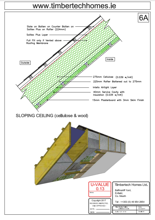
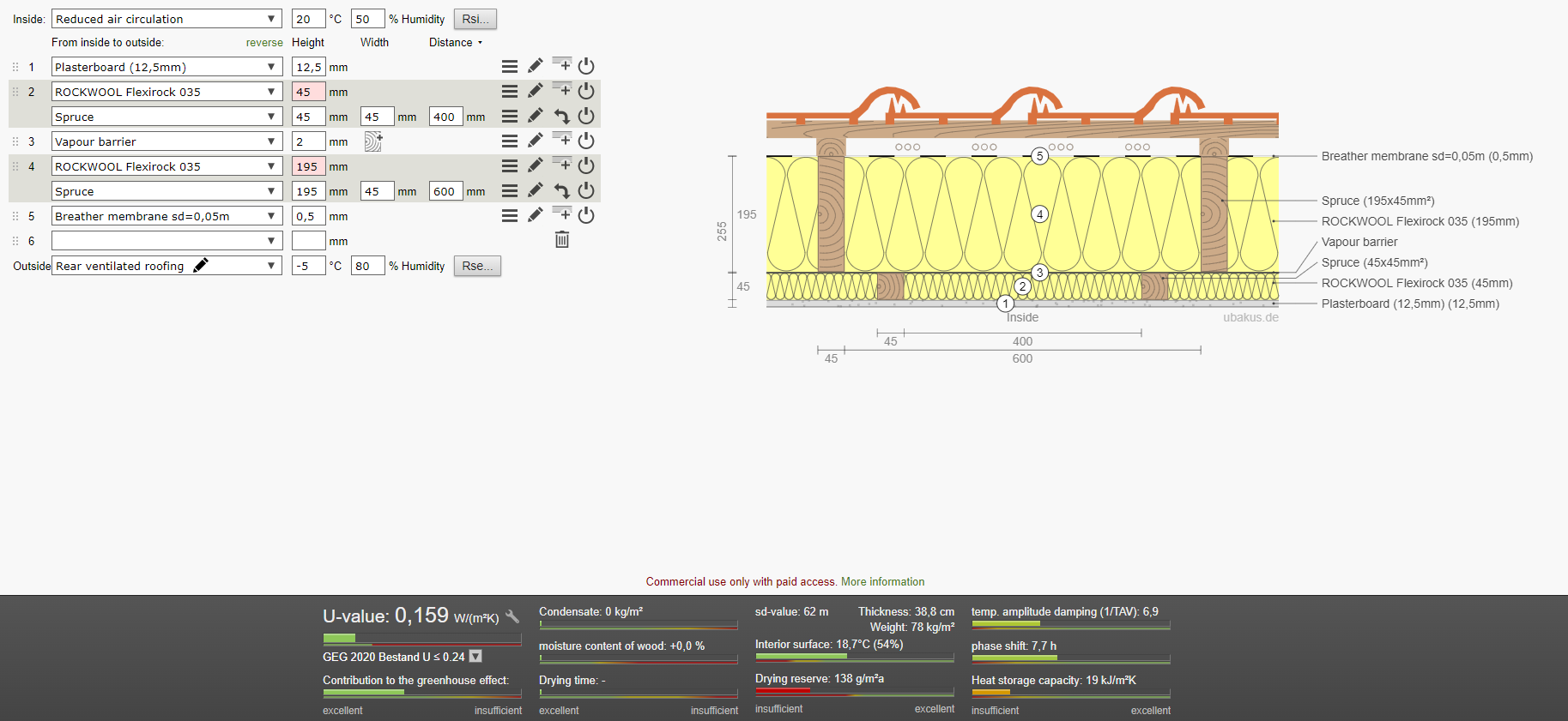
Unless you need racking on both sides I don't think it's necessary. Your SE will know. As far as I know propassive and Medite are both structural racking boards and this type of build up is normally required with timber I joist or double stud walls that require racking on both sides. I don't think it'll be needed on a roof. Again, that's SE territory. For the cost you won't beat glass wool normally but this appears to be a good price for Rockwool (15/m2 inc VAT) which is nicer to work with, better for heat and sound protection. '' The build-up is 12.5mm plasterboard, 45mm battened service cavity with 50mm Rockwool. Vapour Barrier, 195mm rafters full fill with 2x100mm layers of rockwool. Breather membrane taped at all joints. ( it needs to be a suitable breather membrane for this, Tyvek Supro , Siga Majcoat, etc) Batten Counter batten. That will buy you a very cheap and very good roof. Is suspect one of the reasons your builder/carpenter like the idea of ACTIS is that is very easy to handle for them. Easy to cut and light to fit. Fitting insulation by hand is really a pain. Nobody likes it, however rockwool probably one of the best ones. Imagine the glee on their faces if you tell them about blown cellulose! For a 200mm rafter it's €27+VAT installed in Ireland about £22/m2. Again, I would consider 15mm plasterboard ( sound protection, service cavity battens at 600mm cc) Blown cellulose in a 220mm rafter. External OSB racking (durability, strength, sound, rodent protection. Here is a more official drawing from a company that makes nice houses near Dublin. If it helps you to convince anyone.


 1 point
 -
Having tried to insulate my way out of a problem with oversized pipes causing huge dead legs I can confirm that insulating radially run pipes is a complete waste of time. There's so little volume of water in 10/15mm pipes it very very quickly resorts to room temp insulation or not. The incoming mains cold is the only place worth thinking about IMO. Also go to town on all connections to and near the cylinder.1 point
-
No-one likes to hear criticism, but you need to set ground rules for your guests and enforce them. Sounds like your a pain live next door too; if their complaint is to be believed, I would just keep calling the police to complain.1 point
-
0 points
-
You should get planning for a temporary residential caravan, and given your neighbours delight in looking for ways to frustrate you, that would probably be a good idea.0 points
-
No @Happy Valley, but I am going to submit a second application, and then appeal the (almost inevitable) refusal. If nothing else, it'll make good material to post of BH.
 0 points


This leaderboard is set to London/GMT+01:00